

Method and apparatus for injecting water restraint layer of laser shock processing blade
- Summary
- Abstract
- Description
- Claims
- Application Information
AI Technical Summary
Benefits of technology
Problems solved by technology
Method used
Image

Examples
embodiments
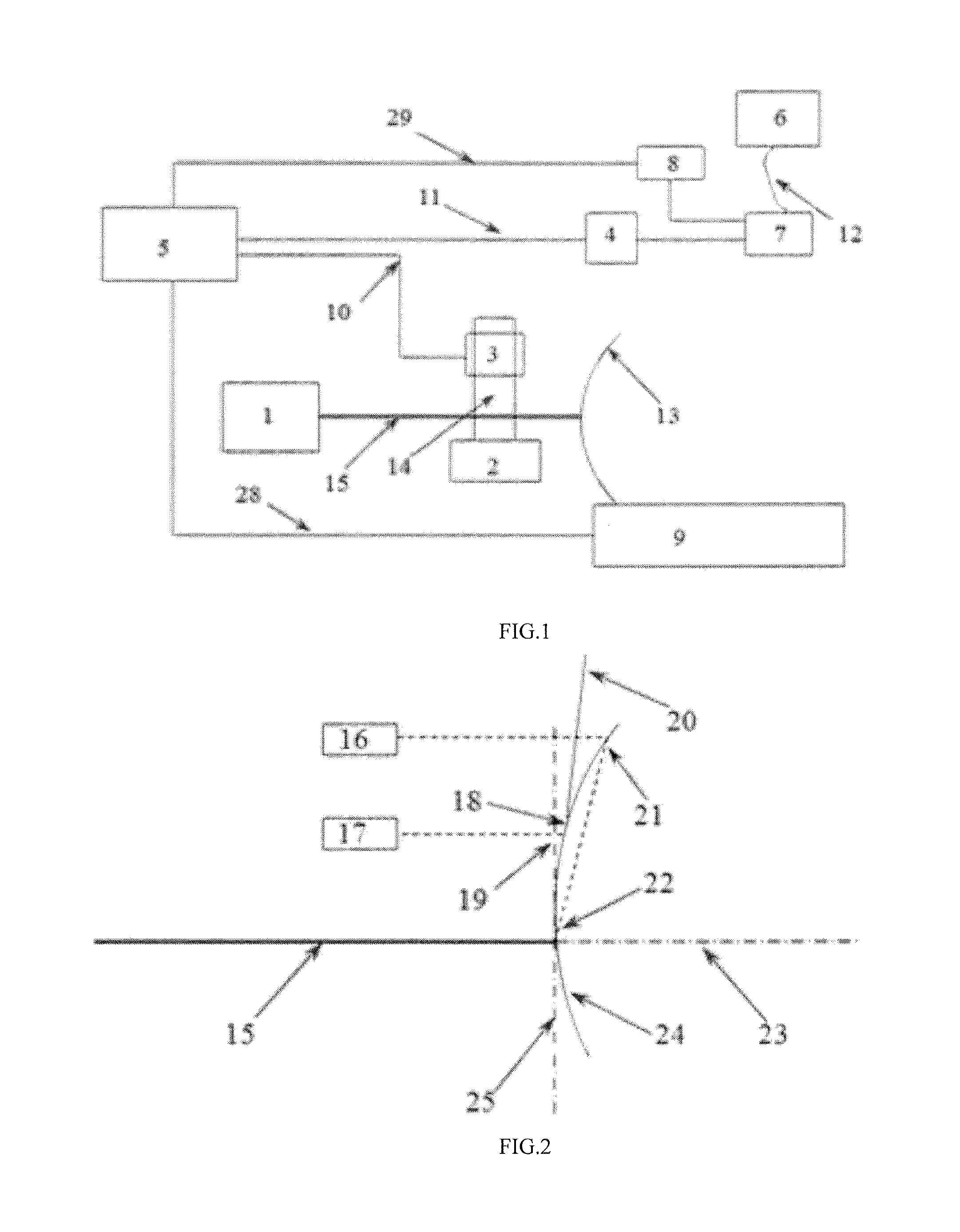
[0028](1) Use holder 14 to fix diastimeter 3 on the diastimeter platform 2, make sure that the vector between detection head I 16 and detection head II 17 is perpendicular to the datum plane 23, and parallel to the laser beam 15; while the vertical distance between detection head II 17 and peening point 22 is 10-20 mm, the horizontal distance between detection head II 17 and peening point 22 is 20-30 mm; adjust the position of detection head I 16 make the vertical distance to the peening point 22 is D2 (D2=D1×2).
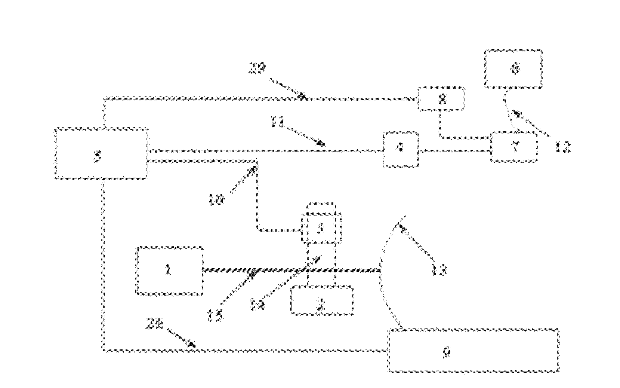
[0029](2) Clamp the blade 13 on the five-axis table 9, control the motion of the five-axis table 9 make the peening point is on the focal point of laser beam 15 and make sure that the tangent plane of peening point 22 is coincide with the work plane 25.
[0030](3) Get two points, which their vertical distance form the peening point 22 is D2 and D1 respectively, and measure their distance to the work plane 25 (L1 and L2), then input L1, L2 to the controller I5; through the prog...
PUM
| Property | Measurement | Unit |
|---|---|---|
| Length | aaaaa | aaaaa |
| Angle | aaaaa | aaaaa |
| Length | aaaaa | aaaaa |
Abstract
Description
Claims
Application Information