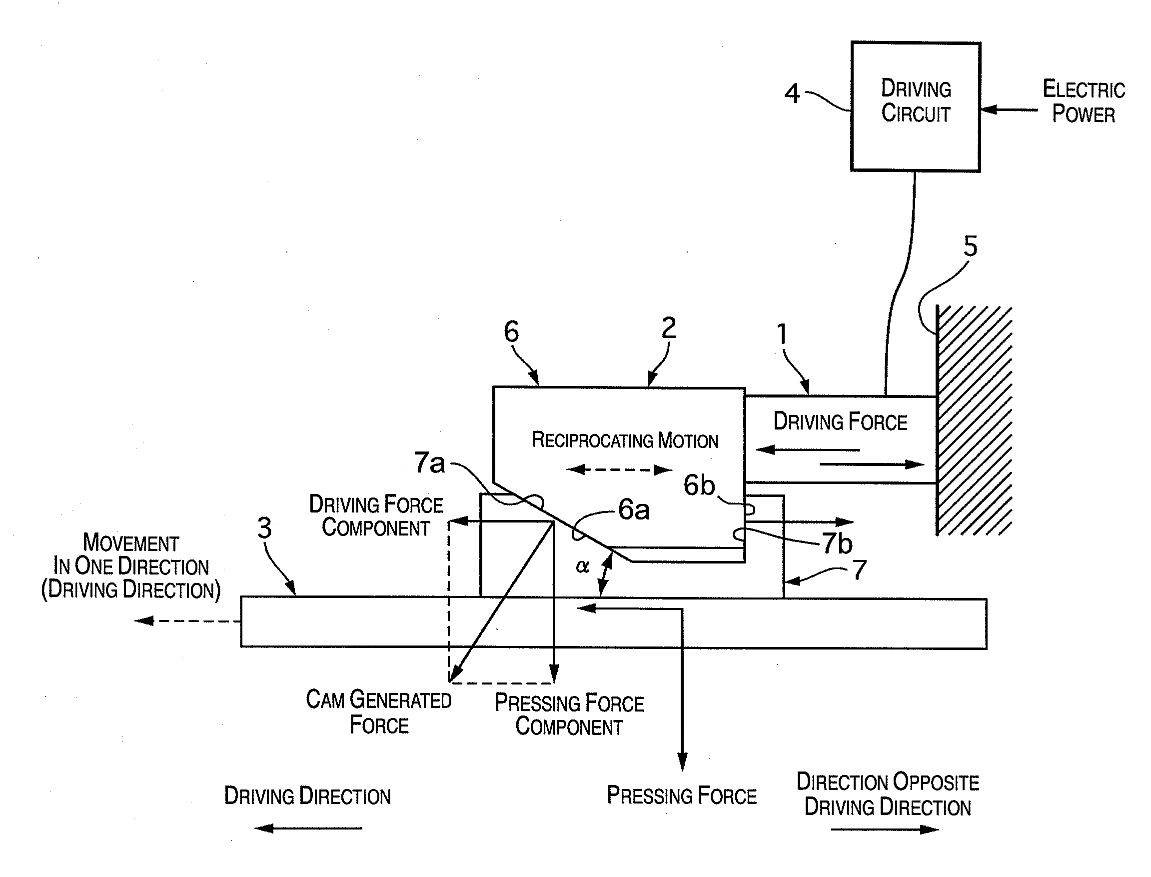
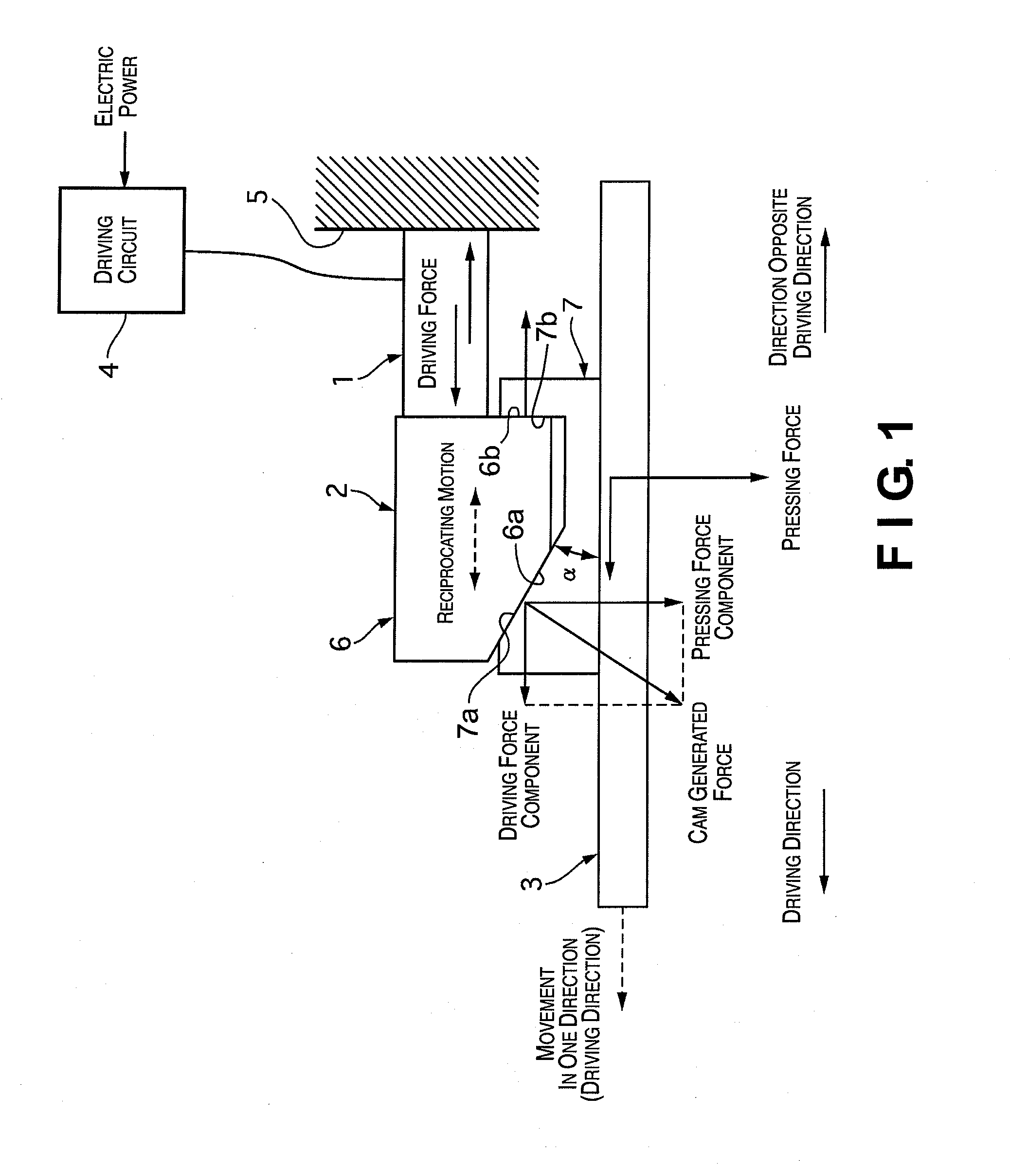
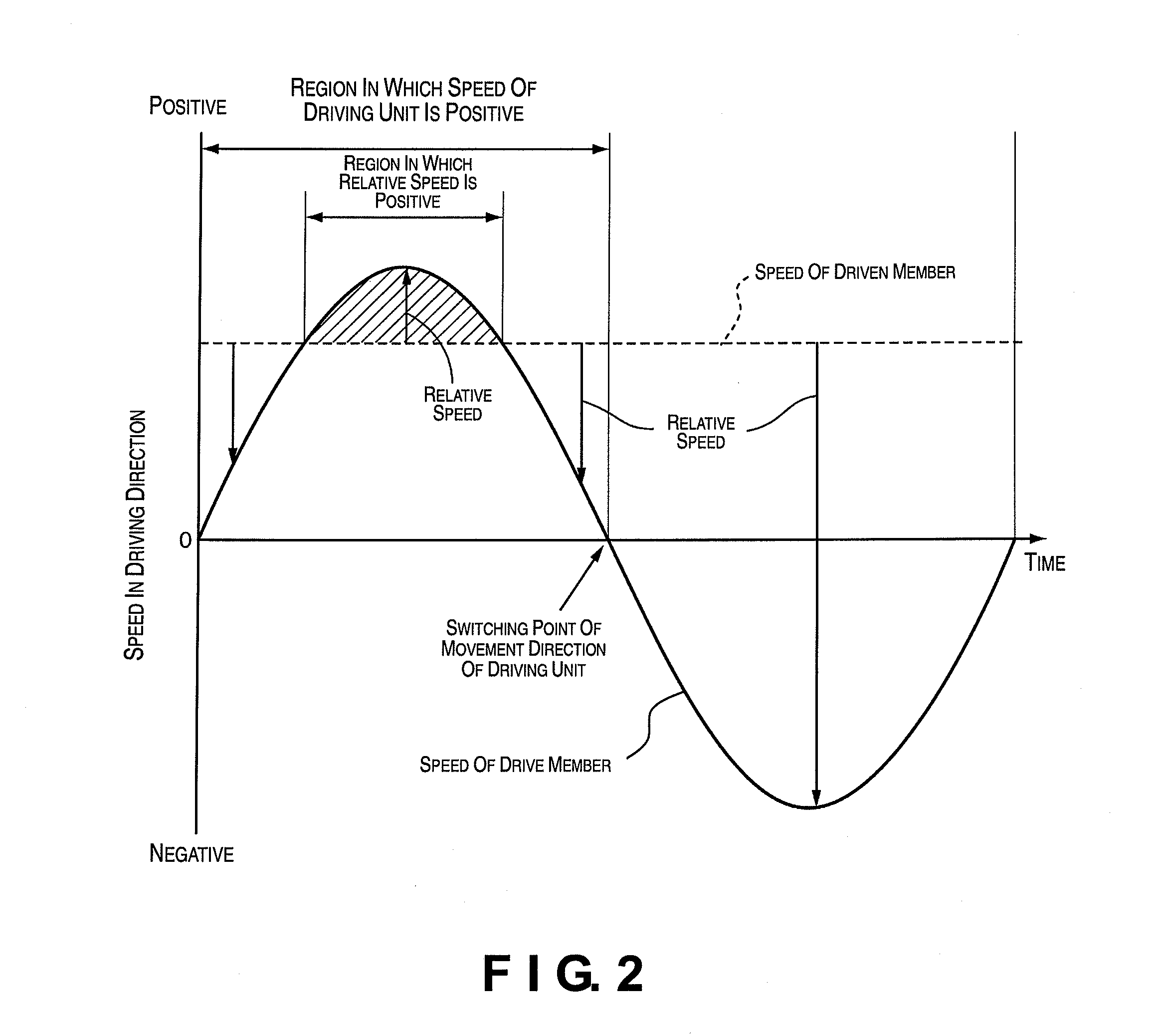
Driving device
a technology of driving device and driving shaft, which is applied in the field of driving devices, can solve the problems and the power consumption of the conventional driving device is relatively large, and achieves the effect of increasing the size and cost of manufacturing increasing the power consumption of the conventional driving devi
- Summary
- Abstract
- Description
- Claims
- Application Information
AI Technical Summary
Benefits of technology
Problems solved by technology
Method used
Image
Examples
second embodiment
[0050]Referring now to FIG. 3, a driving device in accordance with a second embodiment will now be explained. In view of the similarity between the first and second embodiments, the parts of the second embodiment that are identical to the parts of the first embodiment will be given the same reference numerals as the parts of the first embodiment. Moreover, the descriptions of the parts of the second embodiment that are identical to the parts of the first embodiment may be omitted for the sake of brevity.
[0051]The driving device of the second embodiment differs from the driving device of the first embodiment in that a driving unit 11 of the driving device of the second embodiment is configured and arranged to selectively switch the driving direction of the driven member 3.
[0052]FIG. 3 is a simplified side elevational view of the driving device in accordance with the second embodiment of the present invention. As shown in FIG. 3, the driving device of the second embodiment includes th...
third embodiment
[0061]Referring now to FIG. 4, a driving device in accordance with a third embodiment will now be explained. In view of the similarity between the first and third embodiments, the parts of the third embodiment that are identical to the parts of the first embodiment will be given the same reference numerals as the parts of the first embodiment. Moreover, the descriptions of the parts of the third embodiment that are identical to the parts of the first embodiment may be omitted for the sake of brevity.
[0062]The driving device of the third embodiment differs from the driving device of the first embodiment in that a driving unit 16 and a driven member 19 of the driving device of the third embodiment are configured and arranged such that a reaction force of the pressing force is cancelled out.
[0063]FIG. 4 is a pair of diagrams (a) and (b) illustrating a simplified side elevational view (the diagram (a)) of the driving device and a simplified rear elevational view (the diagram (b)) of the...
fourth embodiment
[0070]Referring now to FIGS. 5 and 6, a driving device in accordance with a fourth embodiment will now be explained. In view of the similarity between the third and fourth embodiments, the parts of the fourth embodiment that are identical to the parts of the third embodiment will be given the same reference numerals as the parts of the third embodiment. Moreover, the descriptions of the parts of the fourth embodiment that are identical to the parts of the third embodiment may be omitted for the sake of brevity.
[0071]The driving device of the fourth embodiment is basically identical to the driving device of the third embodiment except that a spring 22 (pressing force generating part) is provided in a driving unit 20 to impart the pressing force to the driven member 19.
[0072]FIG. 5 is a simplified side elevational view of the driving device in accordance with the fourth embodiment. In fourth embodiment, the first member 17 of the third embodiment is divided into upper and lower first ...
PUM
 Abstract
Description
Claims
Application Information
 - R&D
- Intellectual Property
- Life Sciences
- Materials
- Tech Scout
- Unparalleled Data Quality
- Higher Quality Content
- 60% Fewer Hallucinations
Browse by: Latest US Patents, China's latest patents, Technical Efficacy Thesaurus, Application Domain, Technology Topic, Popular Technical Reports.
© 2025 PatSnap. All rights reserved.Legal|Privacy policy|Modern Slavery Act Transparency Statement|Sitemap|About US| Contact US: help@patsnap.com


