
Tire Condition Detection Device

a technology for condition detection and tires, which is applied in the direction of tires, vehicle components, transportation and packaging, etc., can solve the problems of great decrease in workability and troublesome wiring of devices, and achieve the reduction of failures due to wire breakage, shortening the wiring distance from the receiving antenna to the receiver, and facilitating wiring

Inactive Publication Date: 2007-12-27
THE YOKOHAMA RUBBER CO LTD
View PDF2 Cites 5 Cited by
  • Summary
  • Abstract
  • Description
  • Claims
  • Application Information

AI Technical Summary

Benefits of technology

[0011] An object of the present invention is to provide a tire condition detection device in which wiring is facilitated and failure due to breaking of wire is improved.
[0013] According to the present invention, by using the metal part of the vehicle as a waveguide for transmitting the tire condition detection signal from the receiving antenna to the receiver, a wiring distance from the receiving antenna to the receiver can be shortened; therefore, wiring can be facilitated. Failures due to breaking of wire are also reduced because of the reduced wiring distance, allowing failure arising from the breaking to be improved.

Problems solved by technology

When an existing vehicle is wired, a worker stays under the vehicle and does wiring; in the cases of trucks, buses and the like in particular, wiring is very troublesome because a wiring distance from a receiving antenna placed in a tire house for a rear wheel to the receiver is long, which causes a great decrease in workability when the device is installed.
Also, because the vehicle body is long wired at its bottom part facing a road surface, damage thereto by an obstacle may cause breaking of wire or the like; measures against it are required.

Method used


Image

  • Tire Condition Detection Device
  • Tire Condition Detection Device

Examples


Embodiment Construction

[0017] Embodiments of the present invention will be described in detail below with reference to the attached drawings.

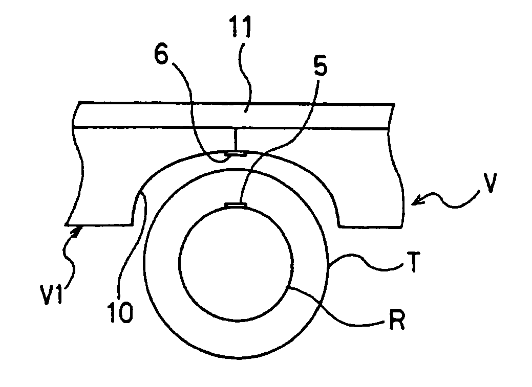
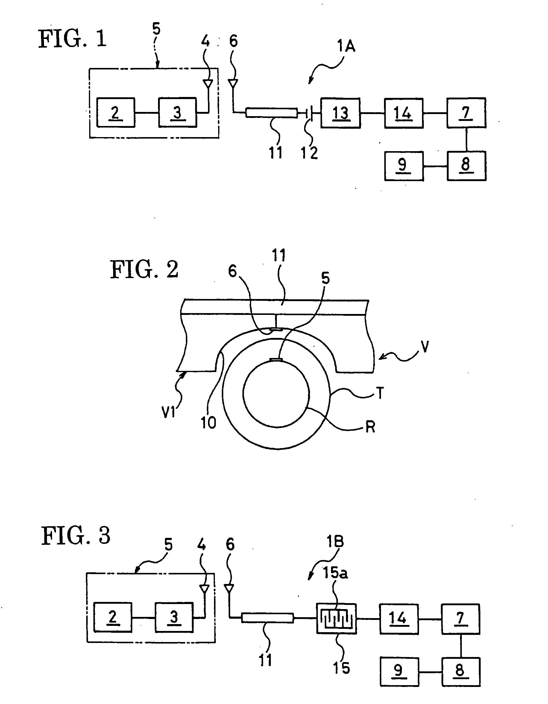
[0018] Referring to FIG. 1, there is shown an embodiment of a tire condition detection device according to the present invention; this tire condition detection device 1A includes a pressure sensor 2 for detecting an air pressure of a tire T of a vehicle V (see FIG. 2), a transmitter 3 and transmitting antenna 4 for transmitting a signal (tire condition detection signal) of pressure detected by the pressure sensor 2, and a power source (not shown) for supplying electric power to the pressure sensor 2 and the transmitter 3. These pressure sensor 2, transmitter 3, transmitting antenna 4 and power source constitute a tire side attachment unit 5, which is designed to be mounted on a tire T side such as the outer circumferential surface of a rim R as shown in FIG. 2, or the inner surface of the tire T.

[0019] The tire condition detection device 1A further includes a recei...


PUM


Abstract

A tire condition detection device is arranged such that a tire condition detection signal detected on a tire side of a vehicle is received by a receiving antenna and entered into a receiver on the vehicle body side of the vehicle. The receiving antenna and the receiver are electrically connected to each other via a metal part of the vehicle. The tire condition detection signal received by the receiving antenna is transmitted to the receiver via the metal part used as a waveguide.

Description

TECHNICAL FIELD [0001] The present invention relates to tire condition detection devices, and more particularly, to a tire condition detection device in which wiring is facilitated and failure arising from breaking of wire is improved. TECHNICAL BACKGROUND [0002] In order to increase safety of vehicles, there have been conventionally proposed various devices which detect physical values showing the usage conditions of a tire such as air pressure and temperature of the tire during running (see patent documents 1, 2 and 3, for example). Such tire condition detection devices each have a sensor, transmitter, transmitting antenna, etc. which are mounted on a tire side, and a receiving antenna, receiver, display, etc. which are mounted on a vehicle body side; a signal showing a physical value such as air pressure or temperature detected by the sensor is transmitted to the vehicle body side via a radio wave to thereby enable a driver to check the tire condition during running; by finding e...

Claims


Application Information

Patent Timeline
Patent Type & Authority Applications(United States)
IPC IPC(8): B60C23/04
CPCB60C23/0408B60C23/0444B60C23/0432
Inventor UEHARA, TSUYOSHI
Owner THE YOKOHAMA RUBBER CO LTD
Learn More