System and method of use for composite floor

a composite floor and floor technology, applied in the field of composite floor systems, can solve the problems of increasing cost, discontinuous slabs in the current available floor system, and increasing construction costs, so as to facilitate a reduced assembly time on site, reduce construction costs, and reduce costs

Inactive Publication Date: 2008-01-03
NEW JERSEY INSTITUTE OF TECHNOLOGY
View PDF30 Cites 11 Cited by
  • Summary
  • Abstract
  • Description
  • Claims
  • Application Information

AI Technical Summary

Benefits of technology

The patent describes a composite floor system and a way to assemble it before delivering it to a construction site. This design reduces assembly time and costs by using pre-assembled components and common tools and methods. The use of lightweight materials also helps to decrease costs associated with on-site assembly.

Problems solved by technology

The technical problem addressed in this patent is to provide a composite floor system that eliminates the need for expensive and complicated shear connectors, while also allowing for the use of multiple materials in the construction process. Additionally, the invention aims to provide a floor system that reduces the amount of temporary formwork required and increases the load capacity of the floor system.

Method used


Image

  • System and method of use for composite floor
  • System and method of use for composite floor
  • System and method of use for composite floor

Examples


Embodiment Construction

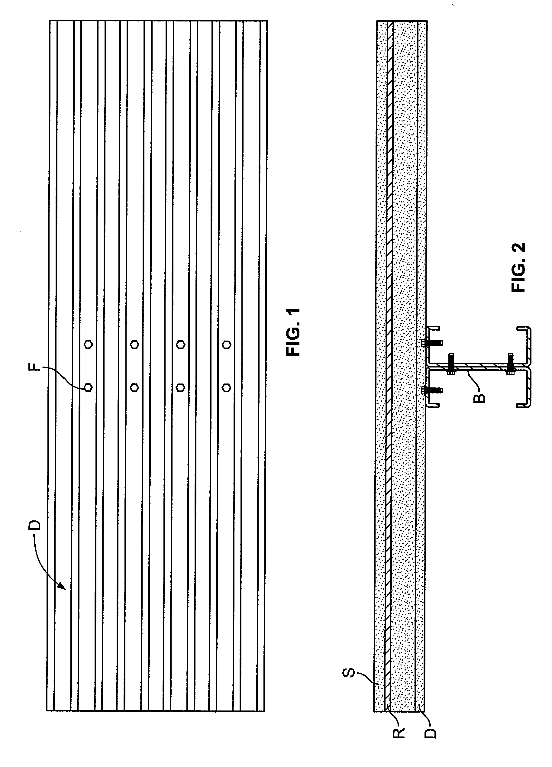
[0036] A composite floor system may include two or more components to allow for transfer of shear forces between the component parts. In some embodiments, multiple components may act as a unified object. Components used in the composite floor system may include lightweight materials, to decrease a total weight of the system while maintaining the strength and durability of the floor system.

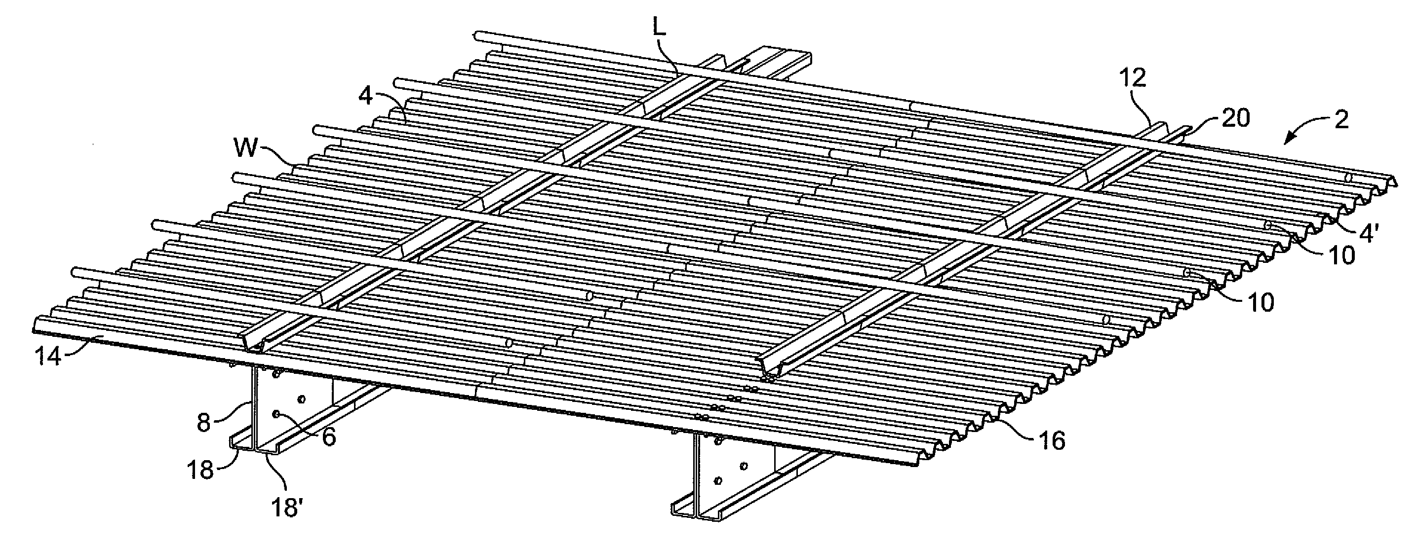
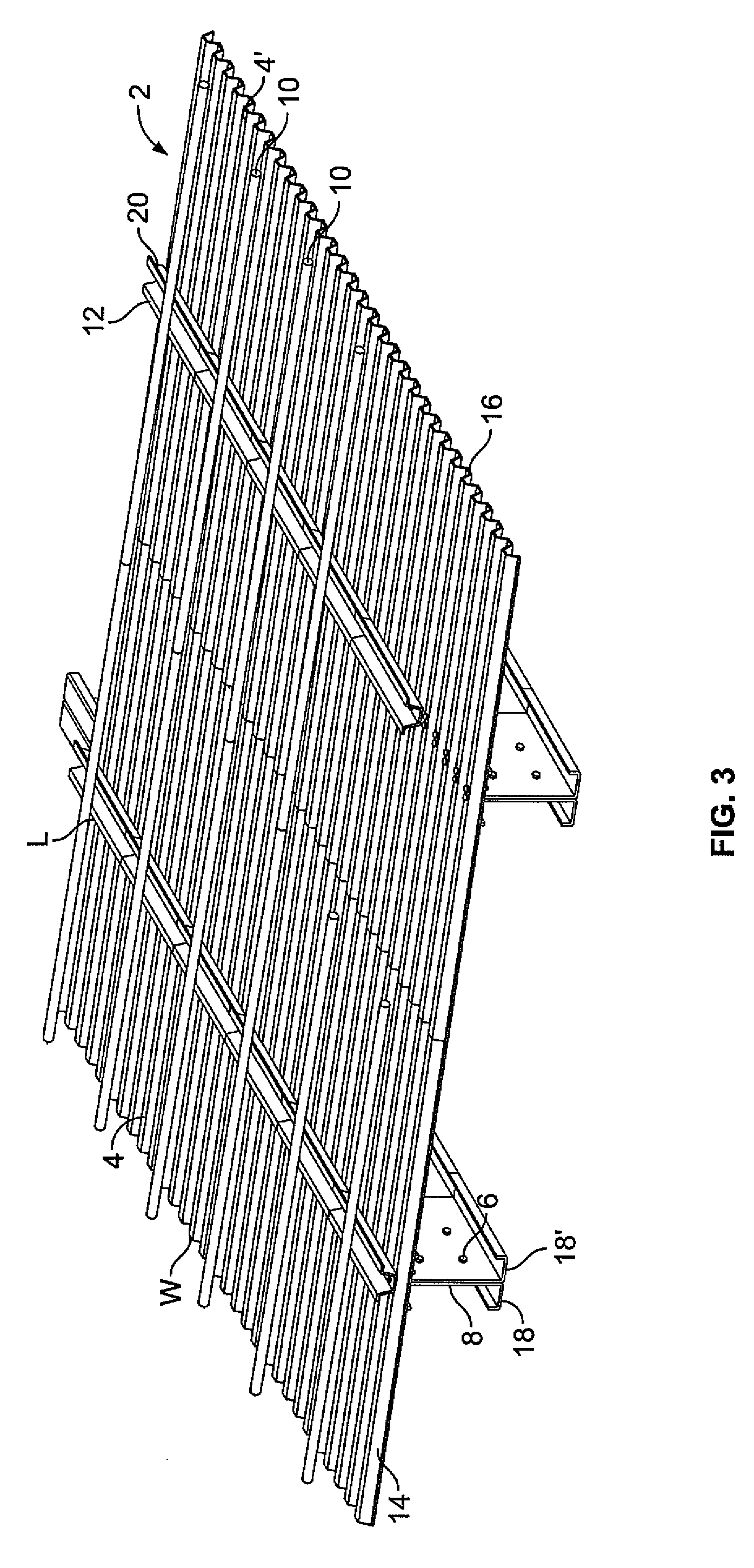
[0037]FIG. 3 depicts an embodiment of composite floor system 2 prior to the addition of a slab. In this embodiment, composite floor system 2 includes decking material 4, 4′ fasteners 6, support members 8, reinforcing members 10, transfer members 12, and a slab (not shown).

[0038] Decking material 4 may include various materials including, but not limited to wood, plywood, fiberboard, metal, corrugated sheet metal, sheet metal (e.g. cold form steel), pre-cast concrete materials, gypsum, Gyp-Crete®, gypsum-metal composites, backer boards, rubber padding, fiberglass, polymer sheets, foam-core panels,...


PUM


Abstract

A system and method of constructing a composite floor system having increased shear transfer between a slab and support members of the system is described. The composite floor system may include any combination of the following elements: a support member, a reinforcing member, a transfer member, a decking material, a fastener, and/or a slab.

Description


Claims


Application Information

Patent Timeline
Owner NEW JERSEY INSTITUTE OF TECHNOLOGY
Why Eureka
Try Eureka