
Spiral pipe machine

a technology of spiral pipe and pipe thread, which is applied in the field of spiral pipe machines, can solve the problems of changing the cross-sectional diameter the need to stop the production of the machine (including the feeding of the web), and the cumbersome and time-consuming task of a round length of ductwork. achieve the effect of automatically changing the diameter of manufactured round ductwork

Inactive Publication Date: 2008-01-03
FORMTEK
View PDF5 Cites 4 Cited by
  • Summary
  • Abstract
  • Description
  • Claims
  • Application Information

AI Technical Summary

Benefits of technology

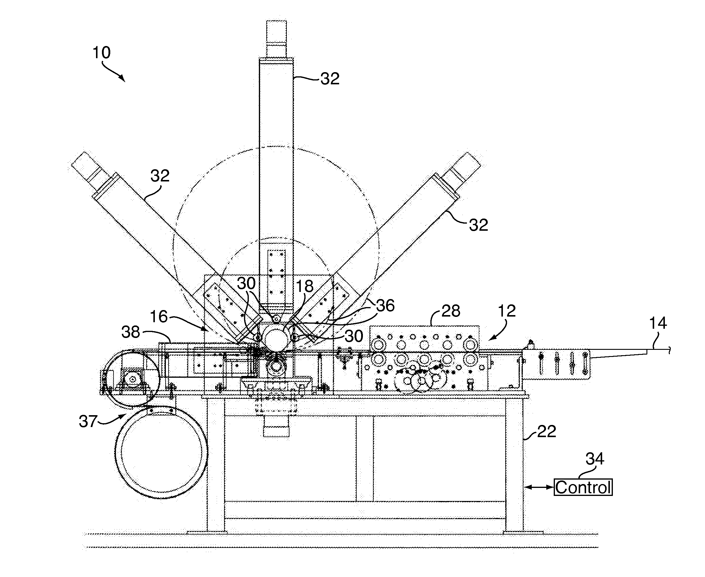
"The present invention provides a spiral pipe machine that can automatically change the diameter of manufactured round ducts without interrupting the operation of the machine. The machine ensures proper alignment of the manufactured pipe and includes a feeding assembly for continuously feeding a web of material and a forming assembly for accepting the web. The controller is capable of controlling the forming station to transition from the first predetermined diameter to the second predetermined diameter during the continuous feeding of the web."

Problems solved by technology

Changing the cross-sectional diameter of a round length of ductwork, however, is a cumbersome and time consuming task, given the present state of the art.
As noted above, the problem with these known spiral pipe machines is that production of the machine (including feeding of the web) must be stopped every time a different diameter of ductwork is desired.
In addition to the lost productivity caused by shutting the machine down, it is also necessary in these known systems to manually change internal mandrels, and the like, in order to facilitate the change in ductwork diameter.
Thus, the known method and apparatus for altering the diameter of a given spiral pipe is time consuming, labor intensive and generally inefficient.

Method used


Image

  • Spiral pipe machine
  • Spiral pipe machine
  • Spiral pipe machine

Examples


Embodiment Construction

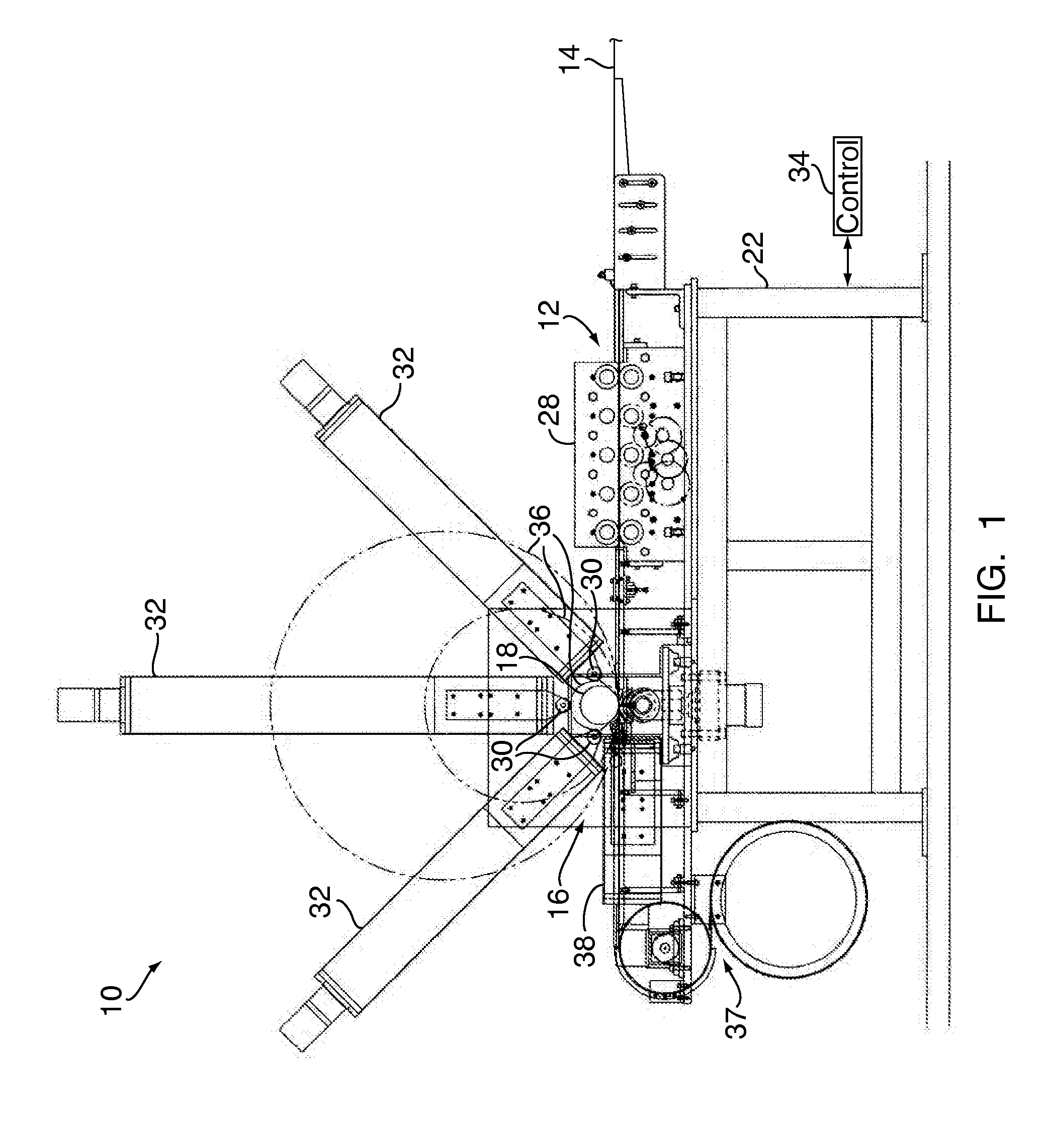
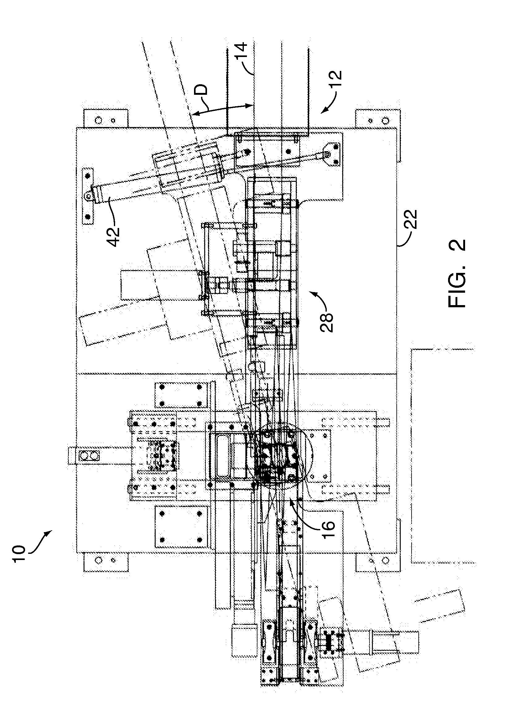
[0024]FIG. 1 is a front-end view of a spiral pipe machine 10, in accordance with one embodiment of the present invention. The spiral pipe machine 10 comprises a feed-in guide assembly 12 (also shown in FIG. 2) for continuously feeding a substantially flattened strip, or web, 14 of material (such as metal) into the machine 10. A multiple roll, spiral pipe-forming apparatus 16 is utilized for forming the strip 14 into a spiral pipe 18 of optionally different diameters. The feeding direction of the web 14, and the output direction of the manufactured spiral pipe, are approximately orthogonal to one another

[0025] It will be readily appreciated that the term ‘spiral pipe’, as utilized herein, refers to a length of metallic ductwork that is manufactured to be substantially round in cross-section. Moreover, it is also known that the seam of the manufactured ductwork defines a spiral, rather than a linear, seam as it extends along the length of the spiral pipe.

[0026] As the components for...


PUM

PropertyMeasurementUnit
diameteraaaaaaaaaa
diameteraaaaaaaaaa
diameteraaaaaaaaaa

Abstract

A spiral pipe machine includes a feeding assembly for continuously feeding a web of material, and a forming assembly for accepting the web. The forming assembly bends the web to form a first section of a spiral pipe having a first predetermined diameter. A controller is employed for selectively instructing the forming means to change its configuration so as to give a second section of the spiral pipe a second predetermined diameter. The controller is capable of controlling the forming station to transition from the first predetermined diameter to the second predetermined diameter during the continuous feeding of the web.

Description

CROSS-REFERENCE TO RELATED APPLICATION [0001] This application is a divisional of U.S. patent application Ser. No. 11 / 398,432, filed on Apr. 5, 2006, titled “SPIRAL PIPE MACHINE,” herein incorporated by reference in its entirety.FIELD OF INVENTION [0002] The present invention relates, in general, to a spiral pipe machine, and deals more particularly with a spiral pipe machine capable of automatically changing the diameter of manufactured round ducts without interrupting the operation of the spiral pipe machine. BACKGROUND OF THE INVENTION [0003] HVAC systems are well known in both residential and commercial environments, and are typically utilized to maintain the environmental conditions within a closed space, such as a building. [0004] A key component of any HVAC system is the ductwork within such a system. Known ductwork can take any particular cross-sectional shape, but is usually either square or round. The ductwork is substantially sealed against ambient environmental contamina...

Claims


Application Information

Patent Timeline
Patent Type & Authority Applications(United States)
IPC IPC(8): B21F3/02
CPCB21C37/16B21C37/124
Inventor DICKINSON, GARY L.
Owner FORMTEK
Learn More