
Powered device including a classification signature resistor

Active Publication Date: 2008-01-03
SKYWORKS SOLUTIONS INC
View PDF7 Cites 14 Cited by
  • Summary
  • Abstract
  • Description
  • Claims
  • Application Information

AI Technical Summary

Benefits of technology

[0010]In yet another particular embodiment, a powered device includes a device classification pin, a classification circuit, a reference current generator, and a current limiter circuit. The device classification pin is responsive to an external resistance. The classification circuit applies a referenc

Problems solved by technology

However, conventional powered devices set only a single current limit that is appropriate for its maximum powering mode.
Typically, the resistance is applied using an e

Method used


Image

  • Powered device including a classification signature resistor
  • Powered device including a classification signature resistor
  • Powered device including a classification signature resistor

Examples


Example

DETAILED DESCRIPTION OF THE DRAWINGS

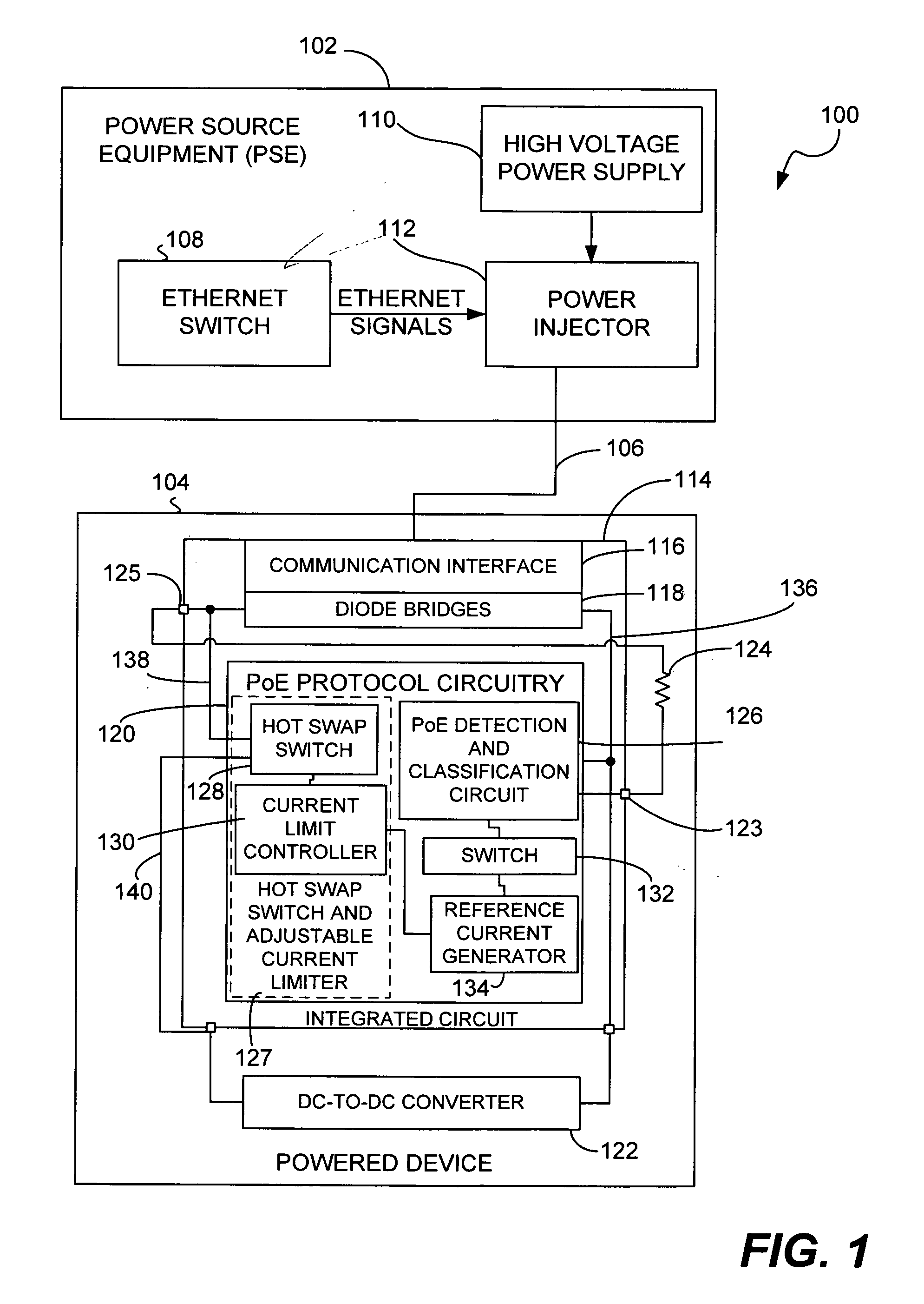
[0016]FIG. 1 is a block diagram of a particular embodiment of a Power over Ethernet (PoE) system 100 including a powered device with an adjustable current limiter. The system 100 includes power sourcing equipment (PSE) 102 and a powered device 104 communicatively coupled by a network cable 106, such as a twisted pair CAT5e Ethernet cable. The PSE 102 may include an Ethernet switch 108, a high voltage power supply 110, and a power injector 112.

[0017]The powered device 104 may include an integrated circuit 114, a DC-to-DC converter 122, and an external resistor 124. The integrated circuit 114 may include a communication interface 116, diode bridges 118, power over Ethernet (PoE) protocol circuitry 120, pins 123 and 125, and voltage supply terminals 136, 138 and 140. The PoE protocol circuitry 120 may include a PoE detection and classification circuit 126, a hot swap switch and adjustable current limiter circuit 127, a switch 132, and a reference cur...


PUM


Abstract

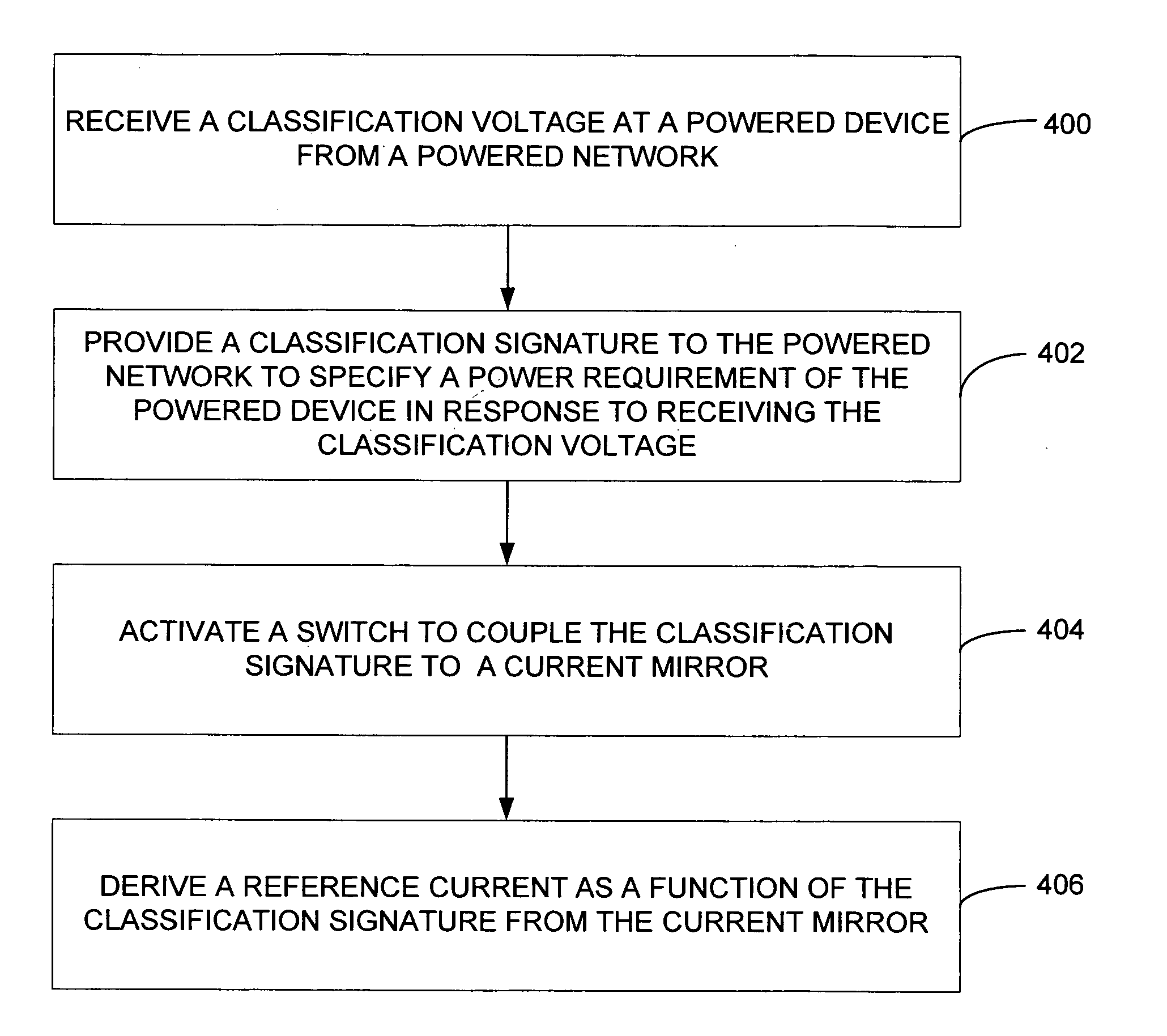
A method is provided that includes receiving a classification voltage at a powered device from a powered network and providing a classification signature to the powered network in response to receiving the classification voltage to specify a power requirement of the powered device. The method further includes deriving a reference current within the powered device and adjusting a current limit as a function of the reference current.

Description

FIELD OF THE DISCLOSURE[0001]The present disclosure is generally related to powered devices in Power over Ethernet networks, and more particularly to powered devices including a classification signature.BACKGROUND[0002]Power over Ethernet (PoE), which is outlined in IEEE Std 802.3™-2005 clause 33 (the PoE standard), refers to a technique for delivering power and data to an electronic device via Ethernet cabling. In a PoE system, power sourcing equipment (PSE) provides a power supply to electronic devices, which may be referred to as powered devices, via an Ethernet cable. PoE eliminates the need for a separate power source to deliver power to attached powered devices. Such powered devices may include voice over Internet protocol (VoIP) telephones, wireless routers, security devices, field devices to monitor process control parameters, data processors, and the like.[0003]The PoE standard specifies that a PSE perform a powered device detection operation to determine whether the powere...

Claims


Application Information

Patent Timeline
IPC IPC(8): G06F1/00
CPCH04L12/10H04L12/40045
Inventor LANDRY, D. MATTHEWAPFEL, RUSSELL J.
Owner SKYWORKS SOLUTIONS INC
Learn More