Method and apparatus for target discrimination within return signals

a return signal and target technology, applied in the field of target detection, can solve problems such as preventing or hindering the identification of desired targets

Active Publication Date: 2008-01-10
PERATON INC
View PDF6 Cites 4 Cited by
  • Summary
  • Abstract
  • Description
  • Claims
  • Application Information

AI Technical Summary

Benefits of technology

[0009]The aforesaid objects may be achieved individually and / or in combination, and it is not intended that the present invention be construed as requiring two or more of the objects to be combined unless expressly required by the claims attached hereto.

Problems solved by technology

When a desired target is part of a scene that includes several targets, the resulting scattering response contains poles from all objects in the illuminated scene, thereby hindering or preventing identification of the desired target.

Method used


Image

  • Method and apparatus for target discrimination within return signals
  • Method and apparatus for target discrimination within return signals
  • Method and apparatus for target discrimination within return signals

Examples


Embodiment Construction

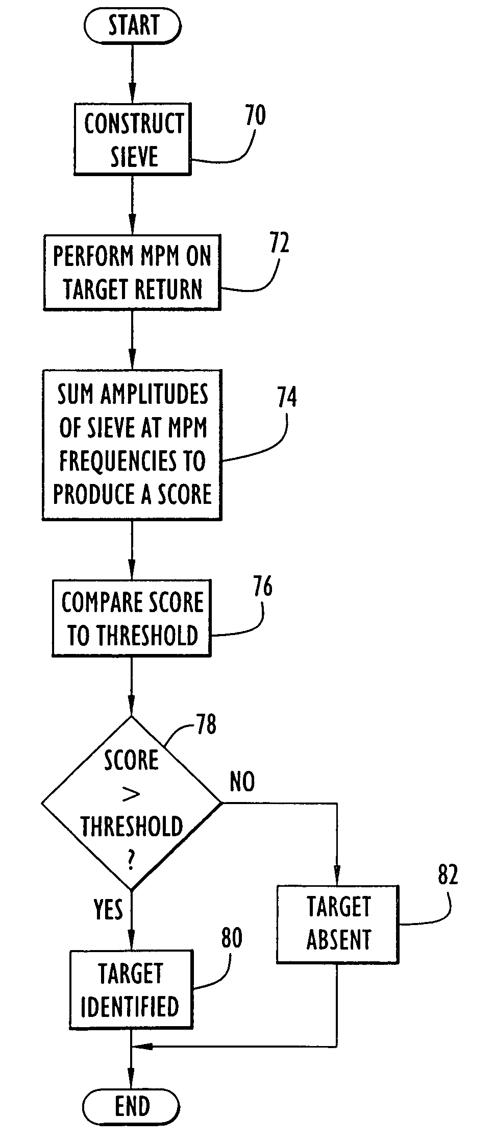
[0018]The present invention enables identification and / or detection of specific targets within an area including a plurality of target objects based on response or return signals produced from illumination of the area by an electromagnetic transmission. A template of pole or damped sinusoid frequencies that represent resonances (e.g., resonant frequencies, etc.) distinctly associated with a desired target is applied to the response signals from the illuminated area. The response signals include poles or damped sinusoid frequencies representing resonances distinctly associated with each of the targets within the area. The template is compared to the mixture of pole or damped sinusoid frequencies within the response signals, thereby yielding a resulting score that indicates the presence of the desired target within the area as described below.

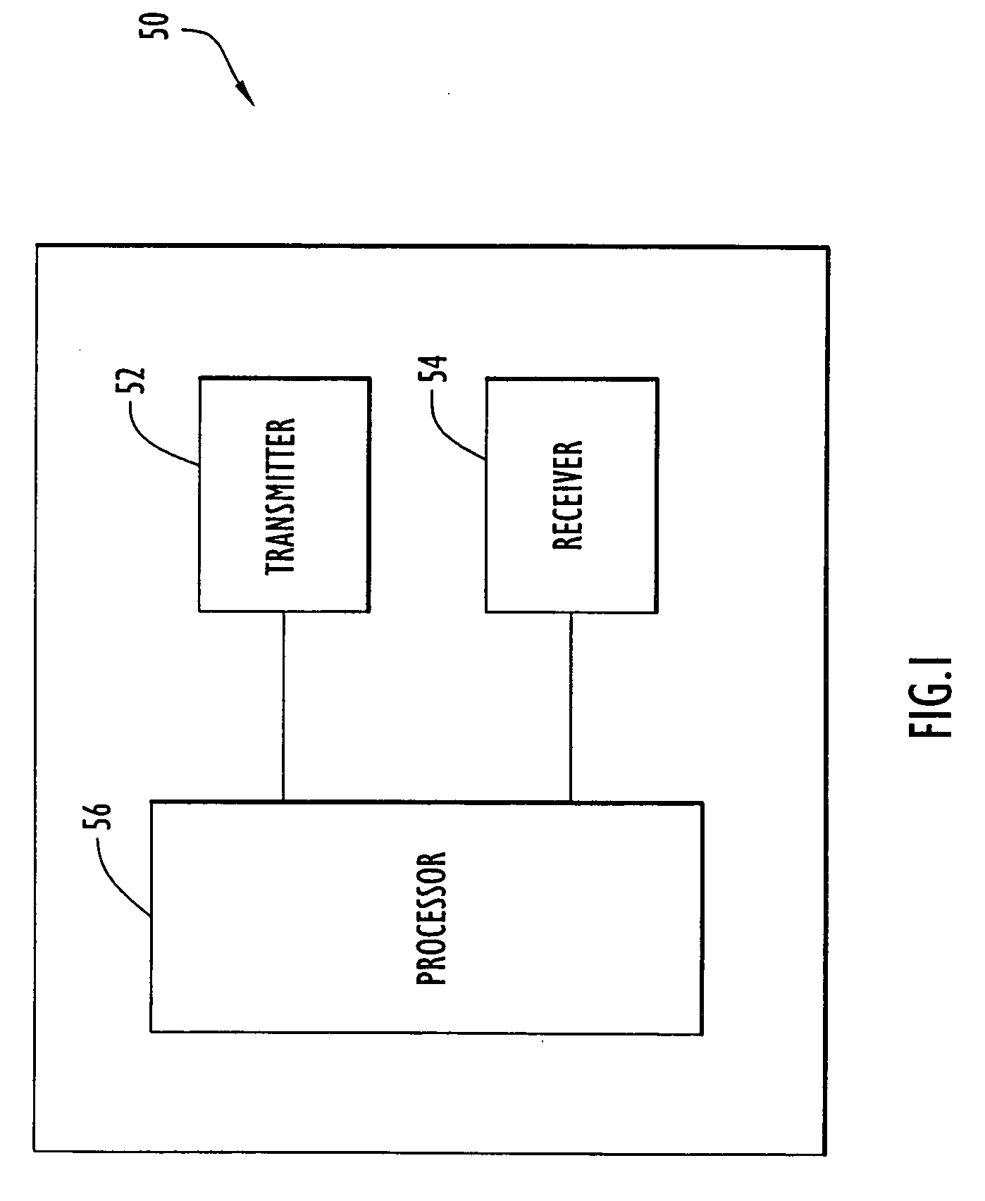
[0019]An exemplary target detection system employing the target discrimination of the present invention is illustrated in FIG. 1. Specifically, ...


PUM


Abstract

A template representing a desired target is applied to response signals from an area including a plurality of targets and illuminated by electromagnetic radiation. The response signals include poles or damped sinusoids representing resonances (e.g., resonant frequencies) distinctly associated with each of the targets within the area. An embodiment of the present invention utilizes pole or damped sinusoid frequencies of a desired target to construct the template or comb-like pattern that is compared to the mixture of pole frequencies within the response signals from the area. The comparison yields a resulting score that indicates the presence of the desired target within the area.

Description

BACKGROUND OF THE INVENTION[0001]1. Technical Field[0002]The present invention pertains to target detection based on return or response signals from an electromagnetic transmission. In particular, the present invention pertains to discriminating targets within response signals from an area including a plurality of targets and illuminated by an electromagnetic transmission.[0003]2. Discussion of Related Art[0004]In order to detect target objects, an object or an area may be illuminated by an electromagnetic field. Electromagnetic signals are reflected from the object or area and received and processed to identify a target object. The scattered response or reflected signals typically exhibit a set of resonances (e.g., resonating frequencies, etc.) that may be represented by damped sinusoids or poles. This pattern is distinctive and may be used to identify the object. Several conventional mathematical techniques may be utilized to determine the parameters (e.g., frequencies, damping co...

Claims


Application Information

Patent Timeline
Patent Type & Authority Applications(United States)
IPC IPC(8): G06K7/00
CPCG01S13/04G01S7/412
Inventor HOFFER, GARYMCLEMORE, DONALD
Owner PERATON INC
Why Eureka
Try Eureka