Hydraulic pressure amplifier

a technology of pressure amplifier and amplifier, which is applied in the direction of pumps, mechanical devices, couplings, etc., can solve the problems of large size of pressure amplifier, large structure space, and relatively heavy weight of pressure amplifier, and achieve the effect of light and compact construction

Active Publication Date: 2008-01-10
MINIBOOSTER HYDRAULICS
View PDF8 Cites 4 Cited by
  • Summary
  • Abstract
  • Description
  • Claims
  • Application Information

AI Technical Summary

Benefits of technology

[0009]It is the object of the present invention to provide a pressure amplifier which is of lighter and more compact construction.

Problems solved by technology

However, the pressure amplifier is relatively heavy and requires a certain structural space.
This type of pressure amplifier is also large and heavy.

Method used


Image

  • Hydraulic pressure amplifier
  • Hydraulic pressure amplifier
  • Hydraulic pressure amplifier

Examples


Embodiment Construction

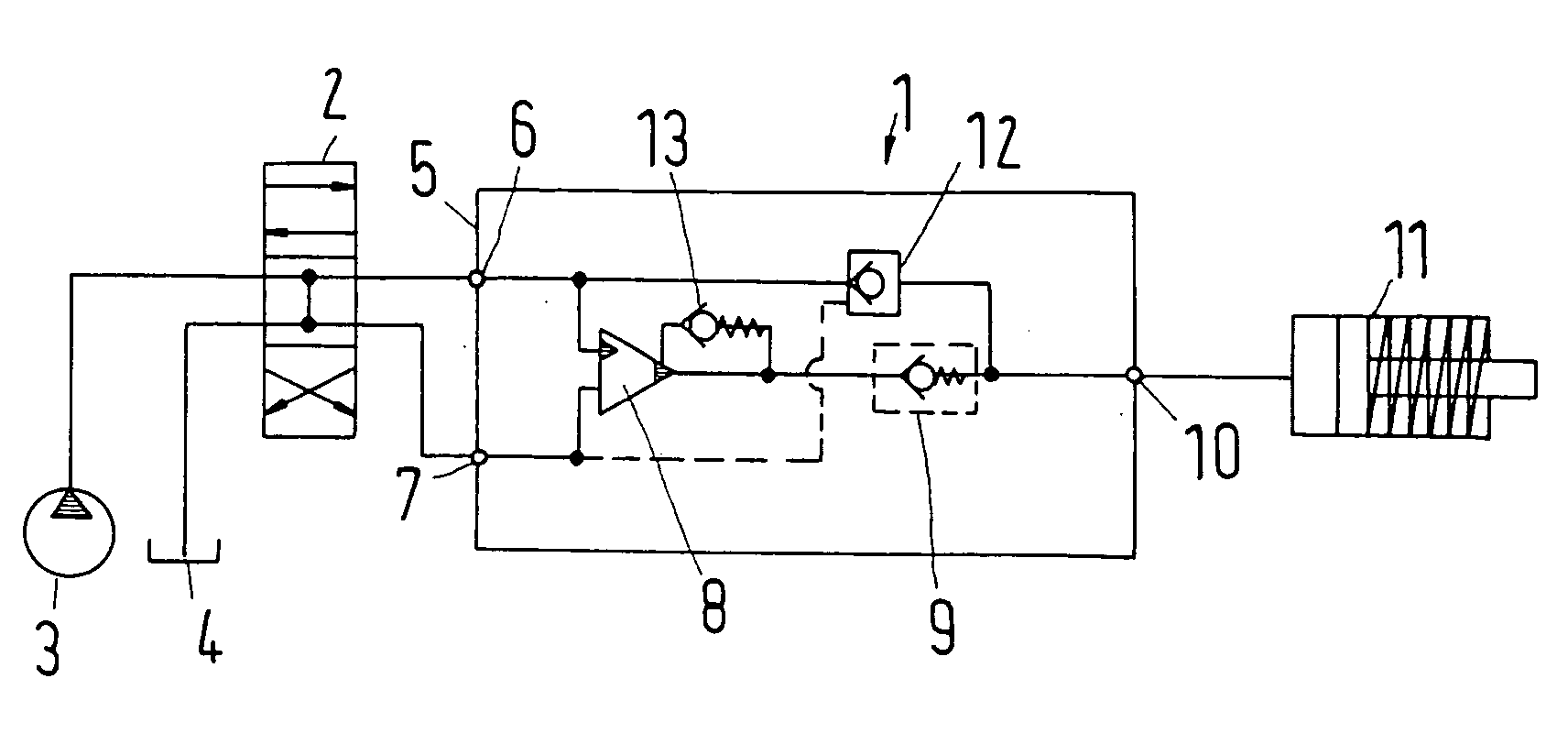
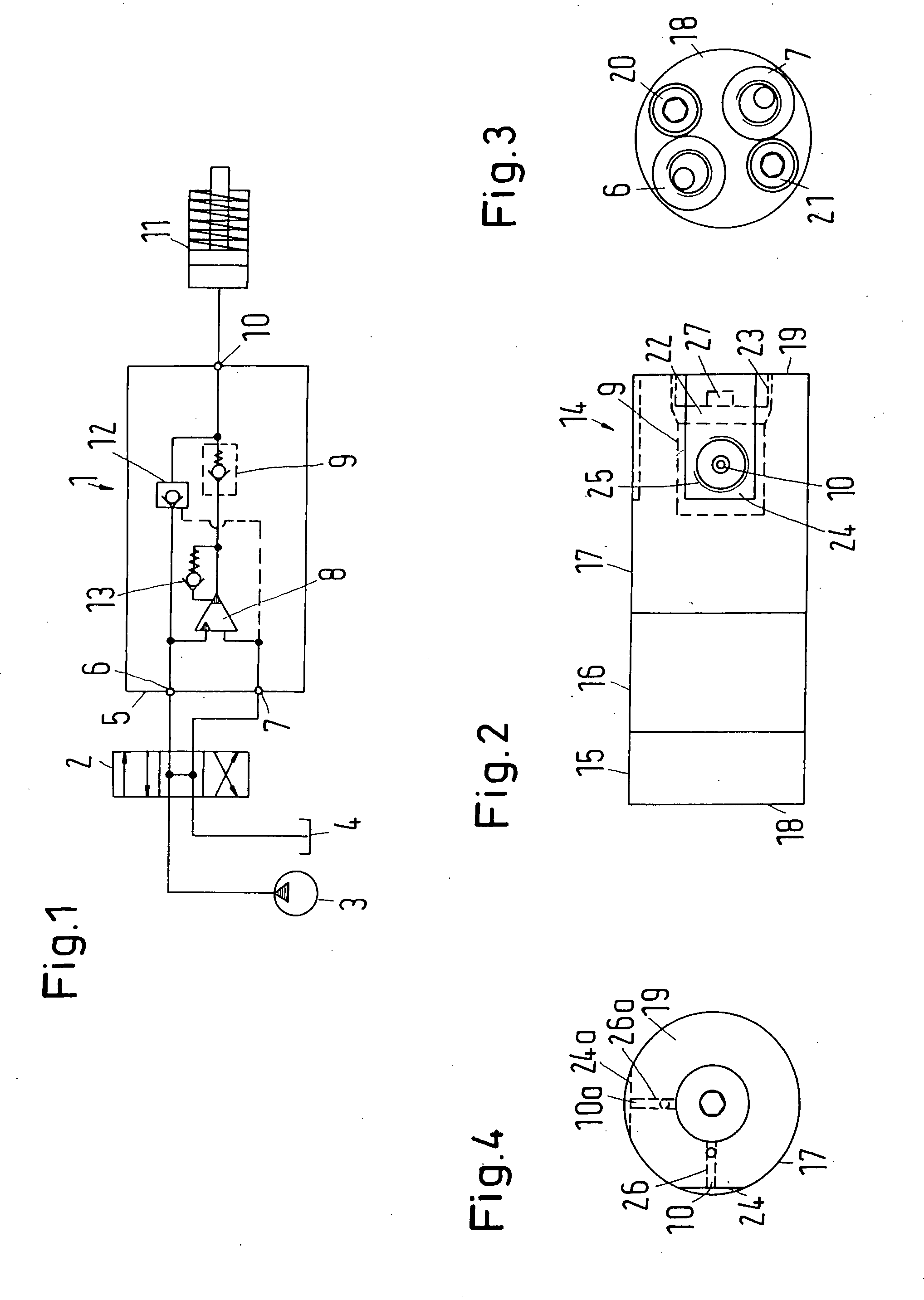
[0031]A pressure amplifier 1 for hydraulic liquid schematically illustrated in FIG. 1 is connected through a switching valve 2 to a pressure source 3, for example, a pump, and to a tank 4. The switching valve is connected to a low pressure side 5 which has a low pressure inlet 6 and a low pressure outlet 7.

[0032]The low pressure inlet 6 is connected to an amplifier 8 which usually is constructed as a stepped piston. The amplifier 8 is connected through an outlet valve 9 to a high pressure outlet 10 which, in turn, is connected to a schematically illustrated user 11.

[0033]In the illustrated embodiment, the pressure amplifier 1 additionally includes a discharge valve 12 which can be regulated through the low pressure outlet 7, and a control valve 13 constructed as a check valve, as is known in the art.

[0034]The functional elements of the pressure amplifier 1, i.e., the amplifier 8, the outlet valve 9, the discharge valve 12 and the control valve 13, are accommodated in a housing 14 wh...


PUM


Abstract

A hydraulic pressure amplifier with a housing which has an end face at a low pressure side and an end face at a high pressure side and a circumferential wall between the two end faces, wherein an outlet valve is arranged adjacent the end face on the high pressure side, and an outlet duct for the hydraulic liquid which is under high pressure. In a pressure amplifier of the above-described type, the outlet duct opens into the circumferential wall or extends through a connection plug which is screwed into the end face on the high pressure side and closes off an assembly duct which receives the outlet valve.

Description

BACKGROUND OF THE INVENTION[0001]1. Field of the Invention[0002]The present invention relates to a hydraulic pressure amplifier with a housing which has an end face at a low pressure side and an end face at a high pressure side and a circumferential wall between the two end faces, wherein an outlet valve is arranged adjacent the end face on the high pressure side, and an outlet duct for the hydraulic liquid which is under high pressure.[0003]2. Description of the Related Art[0004]A pressure amplifier of the above-described type is known, for example, as pressure amplifier HC8 of miniBOOSTER HYDRAULICS A / S, Soenderborg, Denmark.[0005]A pressure amplifier of this type frequently is composed of a lower part with hydraulic connections through which the hydraulic liquid is supplied, an intermediate part and an upper part, wherein the upper part has an outlet at an end face thereof for the hydraulic liquid, wherein the hydraulic liquid has then been placed under high pressure. A capsule w...

Claims


Application Information

Patent Timeline
Patent Type & Authority Applications(United States)
IPC IPC(8): F04F7/02
CPCF15B3/00
Inventor CHAUSEN, PETER J. M.HANSEN, LEIFBOLLMANN, THYGEESPERSEN, CHRISTEN
Owner MINIBOOSTER HYDRAULICS
Why Eureka
Try Eureka