Locking hub and extensible handle assembly

a hub and handle technology, applied in the direction of rod connections, fastening means, animal husbandry, etc., can solve the problems of not being convenient, connection that does not feel firm or secure, etc., and achieve the effect of simple motor skill, greater reach for the device, and more sturdy construction

Active Publication Date: 2020-07-21
CLAM CORP
View PDF30 Cites 6 Cited by
  • Summary
  • Abstract
  • Description
  • Claims
  • Application Information

AI Technical Summary

Benefits of technology

[0004]This disclosure generally provides a locking hub and extensible handle assembly that may be used on devices for which it is advantageous to be able to extend a handle from a retracted position for storage or transport, to an extended position for use. As a further advantage, the handle itself may be telescopic, so as to provide greater reach for the device. In addition, it is preferable to be able to affect locking and unlocking of the handle position relative to a hub using a relatively simple motor skill, such as by squeezing with a hand, regardless of whether or not the hand is gloved. It also is advantageous for the locking hub and extensible handle assembly to have a sliding relationship, for ease of use, while also having a significant overlap and optionally more than one locking element, for a more sturdy construction.
[0005]While the disclosure illustrates the invention in the context of an example landing net device for use in fishing, it will be appreciated that the locking hub and extensible handle assembly may be adapted for use with various devices that have an elongated handle and which may benefit from being able to quickly and conveniently move the handle portion between a retracted position and a secure extended position.

Problems solved by technology

Use of a push button connection between a handle and hub is known, but may require a user to specifically depress the push button with a finger, which may not be convenient when hands are gloved, wet or the device is moving, such as when a fish may be moving within a net.
This may result in a connection that does not feel firm or secure.

Method used


Image

  • Locking hub and extensible handle assembly
  • Locking hub and extensible handle assembly
  • Locking hub and extensible handle assembly

Examples


Embodiment Construction

[0026]For the following defined terms, these definitions shall be applied, unless a different definition is given in the claims or elsewhere in this disclosure. As used in this disclosure and the appended claims, the singular forms “a”, “an”, and “the” include plural referents unless the content clearly dictates otherwise. As used in this disclosure and the appended claims, the term “or” is generally employed in its sense including “and / or” unless the content clearly dictates otherwise.

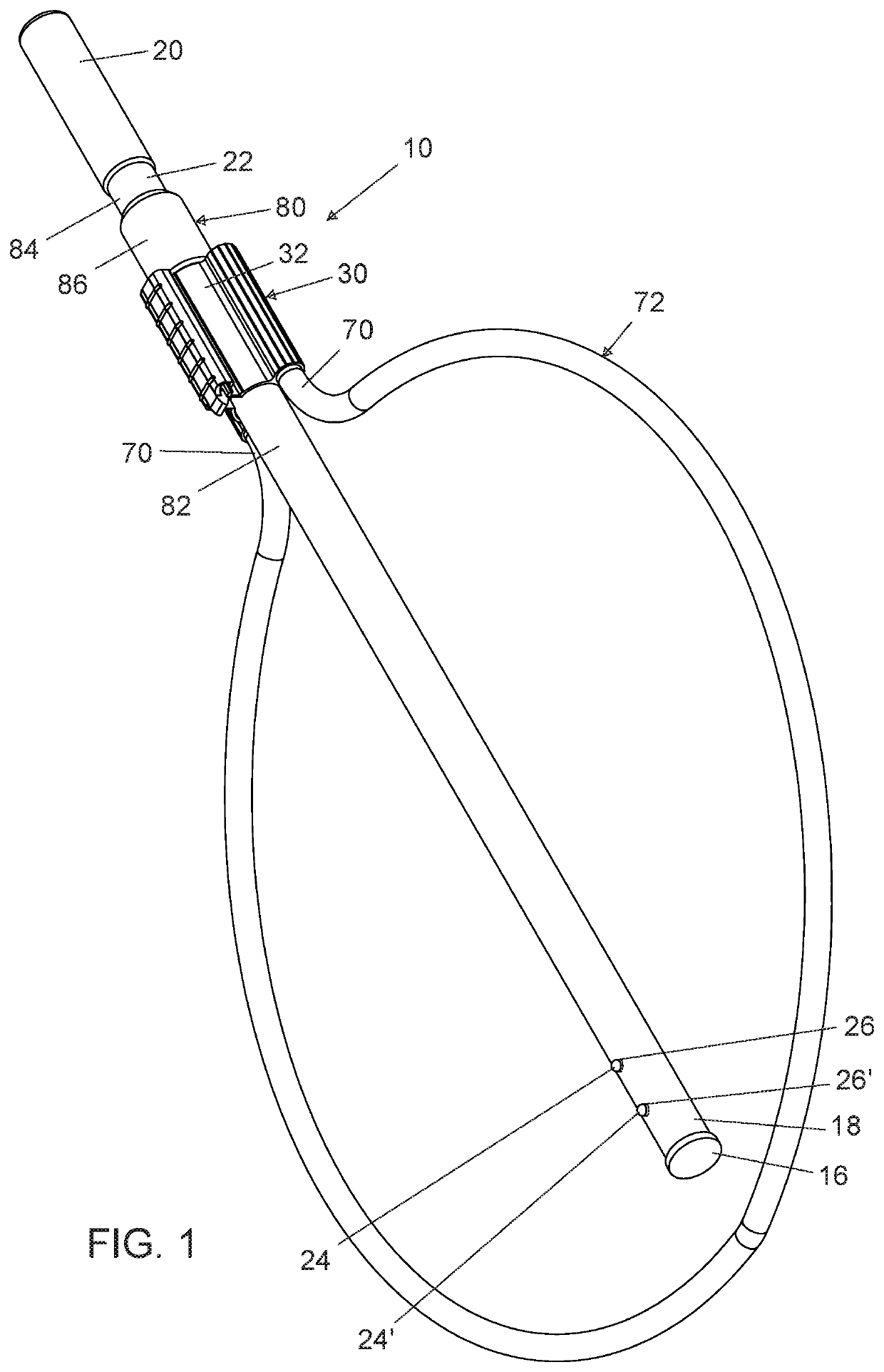
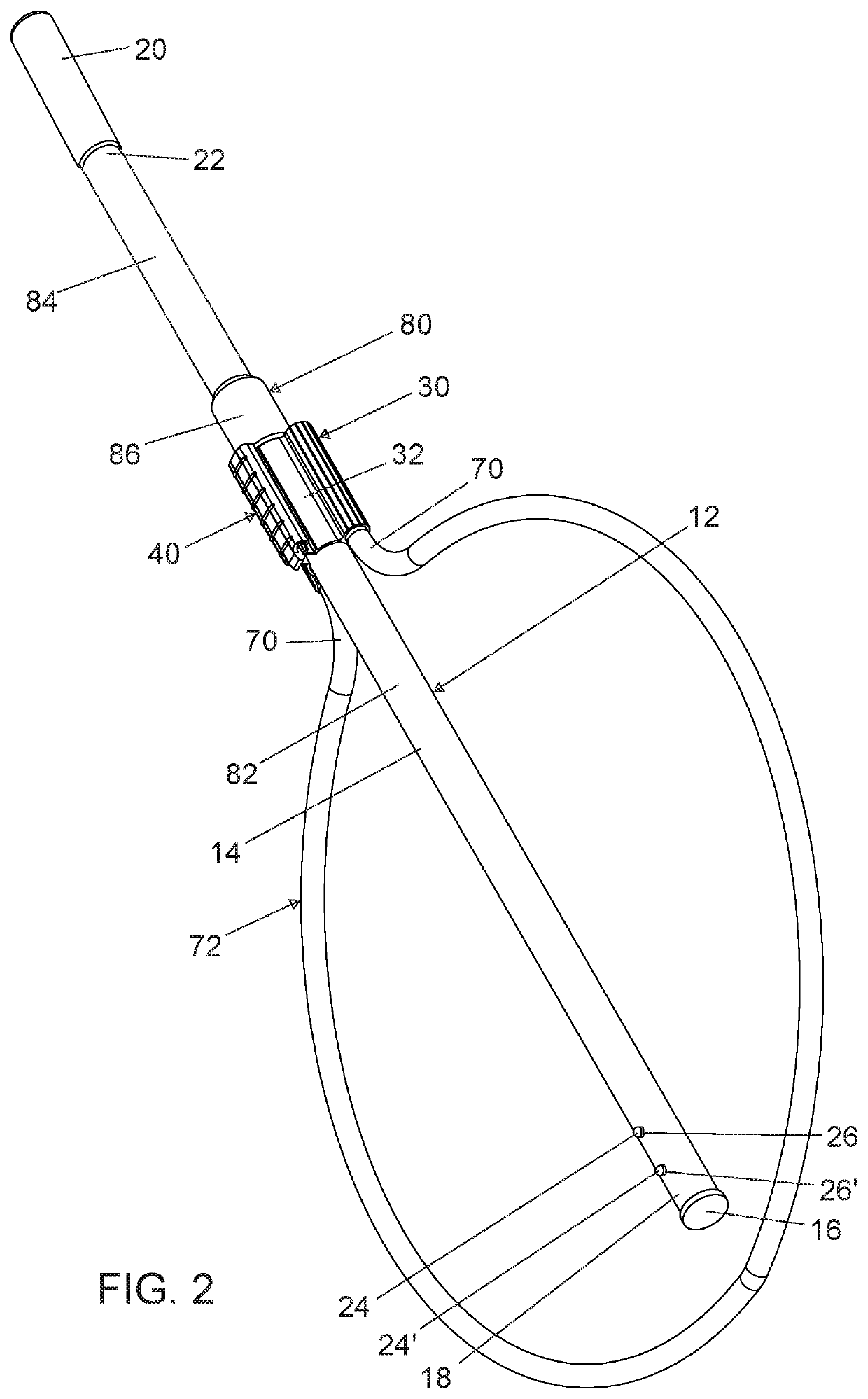
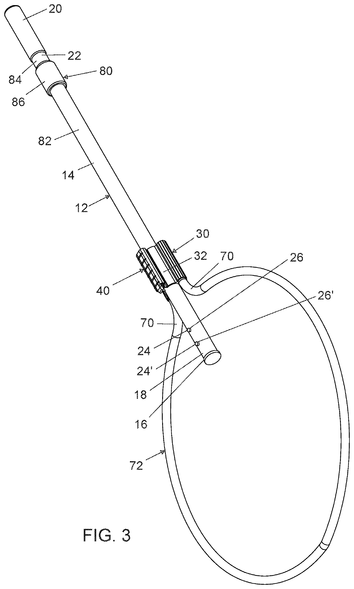
[0027]Referring generally to FIGS. 1-15, it will be appreciated that locking hub and extensible handle devices of the present disclosure generally may be embodied within numerous configurations, and may be used in various devices, such as for example, fish landing nets. Indeed, while acknowledging that all of the example configurations of locking hub and extensible handle assemblies need not be shown herein, an example is provided to better demonstrate that aspects of the invention and that a variety ...


PUM


Abstract

A locking hub and extensible handle assembly includes a handle having an elongated portion with a stop member at a first end, a grasping portion at an opposed second end, and at least one push button within the handle and proximate the first end. The assembly further includes a hub having a body with a passage extending through the body in a longitudinal direction and slidably receiving the elongated portion of the handle. The assembly also includes an actuator that is movable to permit the push button to be used to lock and unlock the handle relative to the hub.

Description

BACKGROUND OF THE INVENTIONField of the Invention[0001]The present invention generally relates to extensible handles, such as may be used in a fish landing net, and more particularly for devices having a handle and hub assembly wherein the handle can be moved relative to the hub from a retracted position to an extended position.Discussion of the Prior Art[0002]There are a variety of devices that use an extensible handle, such as a landing net that may be used to transfer a hooked fish from a fishing line to a bucket, a boat, or back to the water being fished. Use of a push button connection between a handle and hub is known, but may require a user to specifically depress the push button with a finger, which may not be convenient when hands are gloved, wet or the device is moving, such as when a fish may be moving within a net. Known assembly connections using a push button also may have a fairly short overlap between the handle and a hub to which the handle is connected. This may re...

Claims


Application Information

Patent Timeline
Patent Type & Authority Patents(United States)
IPC IPC(8): B25G1/04F16B7/10A01K77/00
CPCF16B7/105B25G1/04A01K77/00
Inventor LAHOOD, JOHN MATTHEW
Owner CLAM CORP
Why Eureka
Try Eureka