Horizontal axis multiple stages wind turbine

a wind turbine and horizontal axis technology, applied in the direction of propulsive elements, engine fuction, propellers, etc., can solve the problems of increasing the power output range, hammering performance capabilities and power output range, and conventional wind turbines not producing the same amount of electricity all the time, so as to increase the rotational speed, reduce the impact, and improve the effect of strength and sturdiness

Inactive Publication Date: 2014-04-24
7142871 CANADA
View PDF12 Cites 1 Cited by
  • Summary
  • Abstract
  • Description
  • Claims
  • Application Information

AI Technical Summary

Benefits of technology

[0010]An enormous advantage of the HMSWT is its turbine blade design and the multiple turbine assemblies which are preferably induced into a reverse rotational movement from one another in a coupling effect. To better explain the operational capability and advantages of this new innovative system one must understand the relationship and interaction between the multiple turbine assemblies. An outer turbine assembly is propelled and forced into a rotational movement propelled by the oncoming wind which in turn induces the second and inner turbine assembly to rotate in an opposite and reverse direction. This effect—called the coupling effect—enables the rotational movement of two or more turbines with the same oncoming wind and airflow. This effect is created by the multiple blades constructed within each of the turbine assemblies. The particular design of these multiple blades not only enhance the propelling force of the wind by increasing rotational movement but simultaneously these blades redirect the same airflow inward increasing the velocity of the airflow and propelling it onto the inner turbine assembly.
[0014]This entirely new technological and innovative concept provides for increased strength and sturdiness, more compact design and construction while simultaneously achieving increased rotational speeds which directly translates into greater production capabilities of electrical energy. This new design incorporating advanced aeronautical blade construction, does not compromise on power output but rather greatly increases operational efficiency and electrical power generation through its capability of operating in adverse conditions with high head winds causing high rotational speeds.
[0015]The HMSWT turbine assemblies' blade design and coupling effect concept will be able to produce greater electrical power output with the same oncoming wind as compared to the conventional wind turbines and will be capable of operating in variable, strong or moderate wind conditions as well as in nonexistent wind conditions. The HMSWT operational capabilities of achieving and sustaining high rotational speeds due to its construction and the coupling effect of the multiple outer and inner turbines enable this new wind turbine concept to produce greater electrical power generation and output. The design innovation may also include and utilize reverse magnetic propulsion to provide a minimum rotational movement in order to enable electrical power production even in the absence of wind.

Problems solved by technology

However, conventional wind turbines and present construction designs have serious operational limitations which hamper their performance capabilities and power output range.
Some of the disadvantages are related to the operational strength of the wind which at times is not constant and varies from zero to storm force.
This means that conventional wind turbines do not produce the same amount of electricity all the time.
The conventional designs and present blade construction cannot withstand excessive rotational forces such as torsion and high tension directly associated with high rotational speeds.
Unfortunately, increased energy and electrical production is directly to and absolutely require high rotational speeds.
The enormous size and wing or blade span is also another huge disadvantage of these conventional wind turbine designs.

Method used


Image

  • Horizontal axis multiple stages wind turbine
  • Horizontal axis multiple stages wind turbine
  • Horizontal axis multiple stages wind turbine

Examples


Embodiment Construction

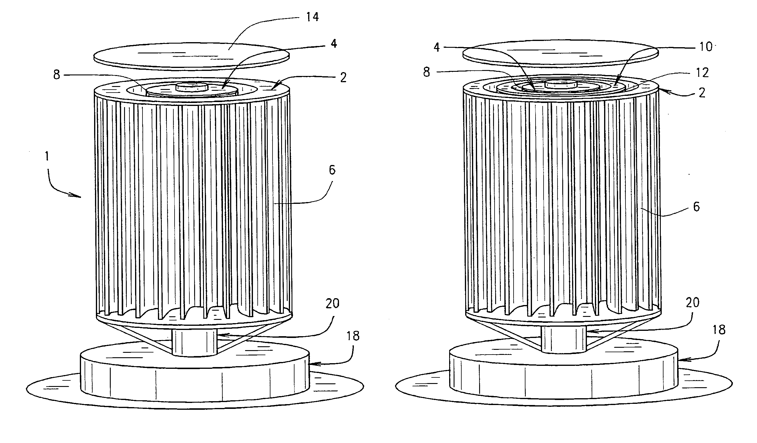
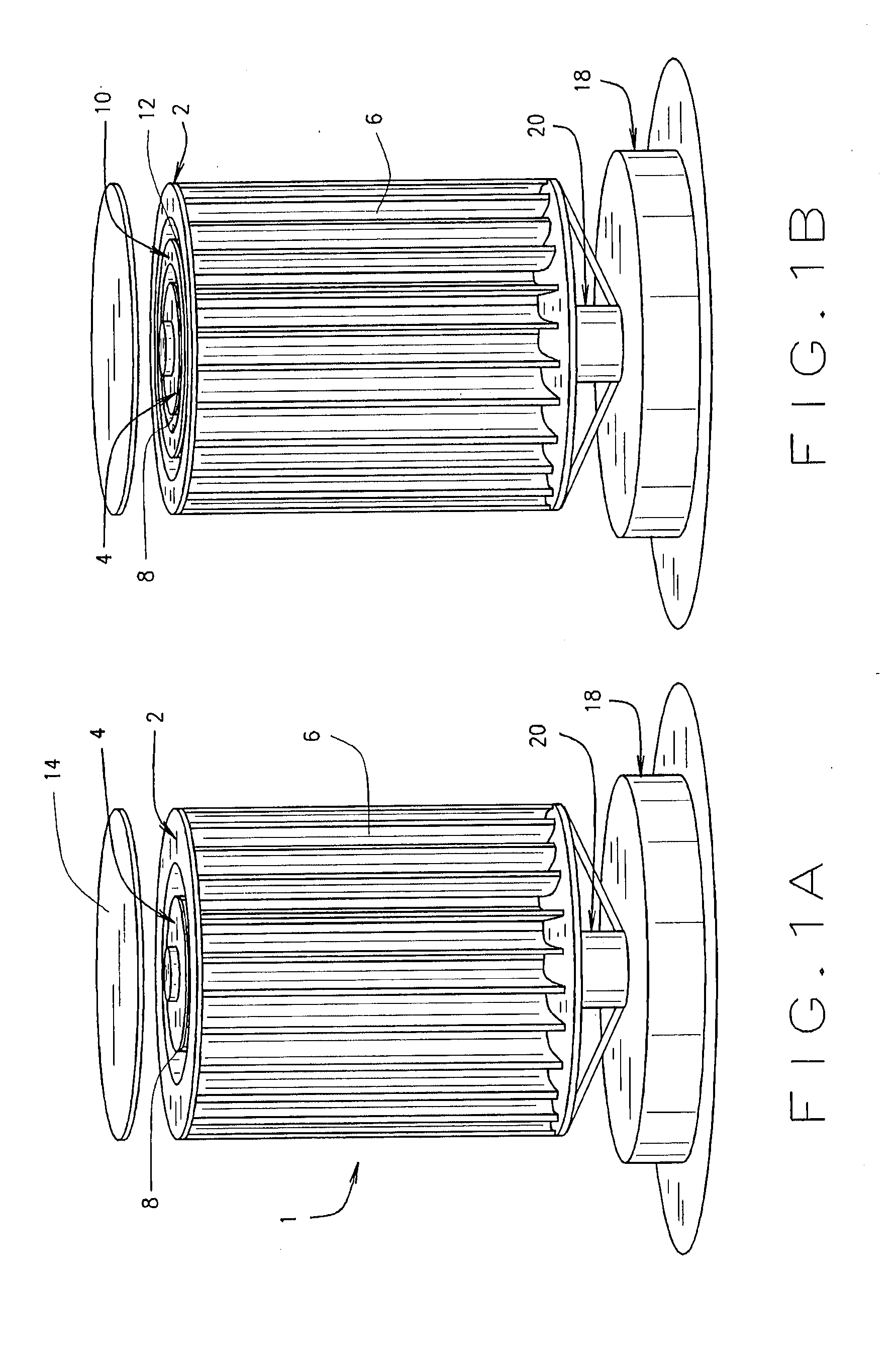
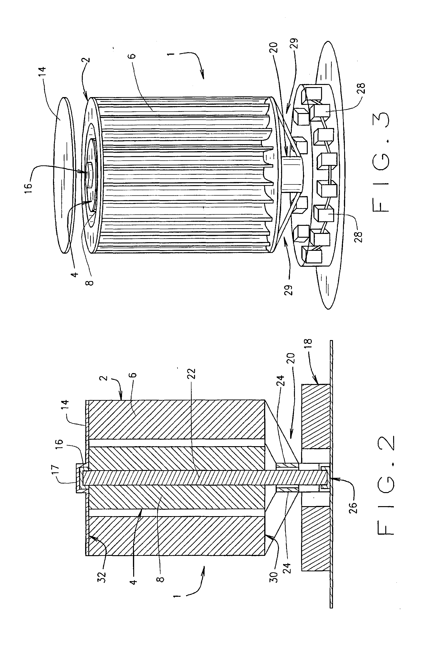
[0030]The present invention relates to a Horizontal Rotational design of Multiple

[0031]Stages Wind Turbine (“HMSWT”). This revolutionary concept and design uses the wind's natural kinetic energy to create a rotational movement which is in turn transformed into mechanical energy and generation of electrical power. It will be explained and understood that the transformation of this kinetic energy from the wind creating rotational movement and mechanical energy into electrical energy is achieved by means of power generating components and accessories such as: multiple turbine assemblies connected to independent shafts which are in turn connected to permanent magnetic alternators which create three phase AC power. This electrical power is then preferably rectified to DC or direct current in order to charge large power storage batteries or feed a grid-synchronous inverter.

[0032]In a preferred embodiment, the turbine blade assemblies may be connected directly to one or several alternators...


PUM


Abstract

An HMSWT is disclosed which is constructed of successive cage type turbine assemblies. The multiple turbine assemblies are preferably induced into a reverse rotational movement from one another in a coupling effect. A first turbine assembly is propelled and forced into a rotational movement propelled by the oncoming wind which in turn induces a second, inner turbine assembly to rotate in an opposite and reverse direction. This coupling effect enables the rotational movement of two or more turbines with the same oncoming wind and airflow. The particular design of these multiple blades not only enhance the propelling force of the wind by increasing rotational movement, but simultaneously redirects the same airflow inward increasing the velocity of the airflow and propelling it onto the inner turbine assembly.

Description

CROSS-REFERENCE TO RELATED APPLICATION[0001]The present application claims priority to and incorporates herein by reference U.S. Provisional Patent Application Ser. No. 61 / 505,506, filed on Jul. 7, 2011.BACKGROUND OF THE INVENTION[0002]A windmill is a machine which converts the energy of wind into rotational energy by means of vanes called sails or blades. The windmill has been used for hundreds of years as a way to harness the earth's power and transform this mechanical movement in order to do work. Wind power has been used as long as humans have put sails into the wind. For more than two millennia wind-powered machines have ground grain and pumped water. In the course of history the windmill was adapted to many other industrial uses. An important non-milling use is to pump groundwater up with wind pumps, commonly known as wind wheels. Wind-powered pumps drained the polders of the Netherlands, and in arid regions such as the American mid-west or the Australian outback, wind pumps p...

Claims


Application Information

Patent Timeline
Patent Type & Authority Applications(United States)
IPC IPC(8): F03D3/02
CPCF03D3/02F05B2250/311Y02E10/74F03D3/061F05B2260/70F01D1/24F03D3/06F03D80/70
Inventor CAGGIANO, MARIO
Owner 7142871 CANADA
Why Eureka
Try Eureka