Modular powder application system

a powder application system and module technology, applied in the direction of liquid spraying plants, spray discharge apparatuses, tribo-charging spraying, etc., can solve the problems of limited use of electrostatic spray guns, limited use of electrostatic spray chambers, and limited use of these technologies for coating moving strips of material, so as to facilitate shaft rotation and reduce powder contamination

Inactive Publication Date: 2005-07-28
MATERIALS SCI CORP
View PDF0 Cites 5 Cited by
  • Summary
  • Abstract
  • Description
  • Claims
  • Application Information

AI Technical Summary

Benefits of technology

[0013] Additionally, the atomizer module has a one-piece weldment shoe pivotable between an operating position and a maintenance or cleaning position. Similarly, the wing is adjustable while installed on the atomizer module, to permit maximum regulation of the powder throughput. The atomizing brush is supported by angular contact bearings, which permit a more taut construction, while achieving a natural vibration that is far higher than the operating speed of the atomizing brush.
[0017] A powder delivery device for delivering powder from a powder feeder to a powder atomizer or to a substrate has a rotatable shaft with a plurality of deformable bristles extending therefrom for conveying powder from a first position to a second position. First and second angular contact bearing assemblies are mounted to the shaft at opposite ends thereof and facilitate rotation of the shaft. First and second seal assemblies are disposed about the shaft in cooperation with the bearing assemblies to reduce contamination of powder during rotation of the shaft.

Problems solved by technology

Electrostatic spray guns are limited by the speed at which the strip may move and the rate at which the powder may be applied.
Similarly, the electrostatic application chambers are limited by the rate at which powder can be applied to the strip, thus limiting use of these technologies for coating moving strips of material.
One drawback to electrostatic application chambers is the service requirements, either on account of routine maintenance or because the powder needs to be changed, as may occur when the type or color of the powder is changed.
In those events, the coating line has to be stopped for an excessively long period, and the electrostatic coating apparatus essentially taken apart.
This greatly limits the utility of the powder application system, and also increases the cost of the resulting coated product.
Typically, a stitch is used to connect the tail end to the lead end, but the stitch may extend from one or both strips by such an extent that it may damage the electrostatic coater when it passes through the coating apparatus.
We have found that auger brushes do not achieve uniform depths of powder in the receptacle, and instead provide more powder proximate the hopper and less powder at the opposite end.
Merely increasing the speed of rotation of the auger brush does not solve this problem, and may instead create a different problem due to the sag in the brush which may occur due to its length.
Such a shoe was relatively lightweight, but the compressive forces were generally insufficient to overcome sag of the shoe due to its length and permitted small gaps to be created at abutting sections.
Efforts to shim the shoe segments and otherwise overcome the effect of sag and the formation of gaps were generally unsuccessful.
Moreover, because of the tight fit of the shoe to the feeder and atomizing brushes, the shoe made cleaning those brushes and the powder application chamber difficult.
The brushes and chamber typically are cleaned with pressurized air, a task made difficult because of the presence and location of the shoe.
Moreover, when supported by radial bearings, as has typically been done, the brush tended to vibrate excessively due to its natural frequency of vibration.
The vibrations tended to damage the equipment, and to throw powder from the atomizer in an uncontrolled way.
In that event, a portion of the strip has a non-uniform surface, and is not commercially saleable.
This was a slow process.

Method used


Image

  • Modular powder application system
  • Modular powder application system
  • Modular powder application system

Examples


Embodiment Construction

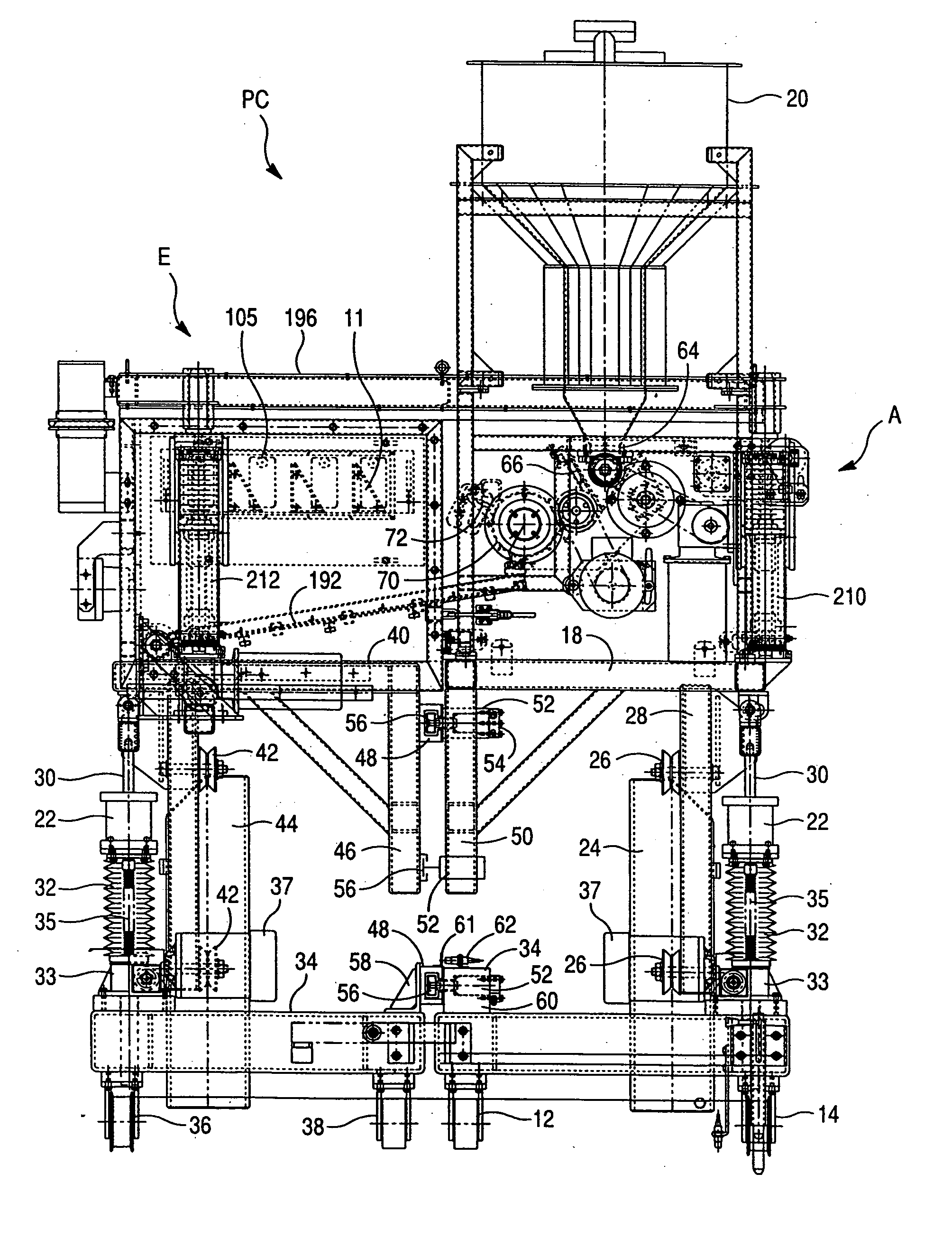
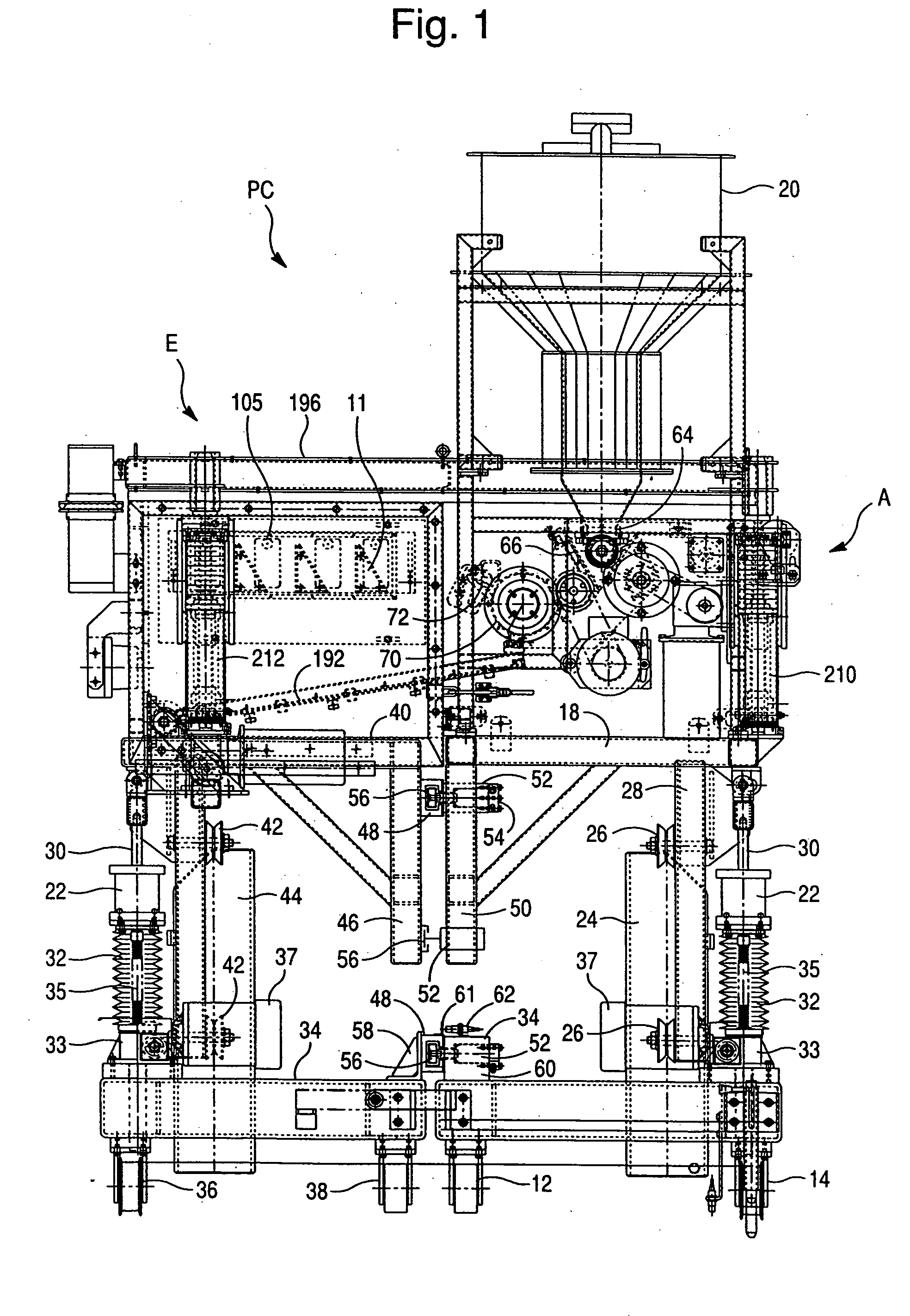
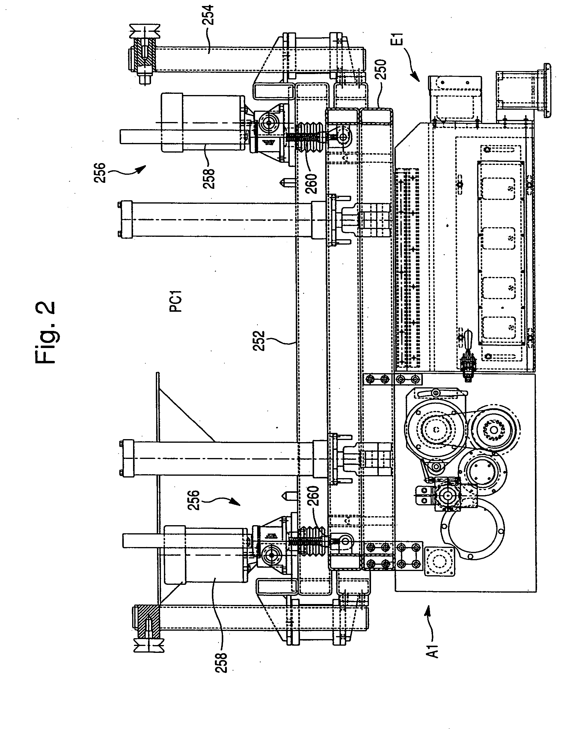
[0054] Powder application system PC of FIG. 1 includes a powder atomizer module A and an adjacently disposed and cooperating electrostatic coating module E. The powder application system PC of FIG. 1 is particularly adapted for electrostatically applying a fine powder, such as powder paint, to a first or lower surface of continuously moving substrate, such as steel sheet. Powder application system PC1 of FIG. 2 likewise has a corresponding powder atomizer module A1 and an adjacently disposed and cooperating electrostatic coating module E1. Powder application system PC1 is particularly adapted for electrostatically applying fine powder, such as powder paint, to continuously moving substrate, such as steel sheet. The powder application systems PC and PC1 are preferably disposed on opposite sides of the moving substrate, and preferably are spaced along the longitudinal or direction of movement of the substrate. Although the powder application systems PC and PC1 are illustrated as apply...


PUM


Abstract

A powder atomizer comprises a rotatable powder conveying brush operably associated with a powder supply. A powder receptacle has an inlet and an outlet. The powder conveying brush extends along the inlet and supplies powder to the receptacle. A rotatable powder metering brush is operatively associated with the outlet and withdraws powder from the receptacle. A rotatable powder atomizing brush is operatively associated with and receives powder from the metering brush and discharges the powder. A shoe is operatively associated with the atomizing brush, and is pivotable about a pivot axis between a first and a second position.

Description

FIELD OF THE INVENTION [0001] The disclosed invention is a modular powder application system for applying powder paint, powder coatings, and like fine powders to moving webs of continuous strip material, such as steel strip. More particularly, the disclosed invention is a powder application system having a powder atomizer module and an electrostatic coating module, with the modules secured together when in an operating condition and adapted to be displaced relative to each other when in a non-operating condition, in order to permit cleaning, service, etc. as may be required. BACKGROUND OF THE INVENTION [0002] The application of powder paint, powder coatings, etc to lengths of continuous moving strip material has been achieved through use of electrostatic spray guns and electrostatic application chambers in which powder, in atomized form, is caused to be attracted to the strip through use of charging electrodes positioned. Electrostatic spray guns are limited by the speed at which th...

Claims


Application Information

Patent Timeline
Patent Type & Authority Applications(United States)
IPC IPC(8): B05C5/00B05DB05D1/00
CPCB05B5/032B05B5/14B05B5/057B05B5/047
Inventor KERBEL, DARRELL A.RHEE, SANGKUMZI, TED B.SHELDON, DON K.FEINER, DEIRK A.PEPEVNIK, MERETHECONYERS, BERNARD Y. III
Owner MATERIALS SCI CORP
Why Eureka
Try Eureka