Al technical title is built by PatSnap Al team. It summarizes the technical point description of the patent document.
a technology of fastening system and panel, which is applied in the direction of walls, mechanical equipment, transportation and packaging, etc., can solve the problems of not providing satisfactory resistance to the hook elements, the connection of the known fastening system is particularly problematic, and the connection ceases to function, etc., to facilitate not only the insertion of the locking element, the effect of simple components
Inactive Publication Date: 2008-01-17
AKZENTA PANEELE PROFILE GMBH
View PDF15 Cites 53 Cited by
Summary
Abstract
Description
Claims
Application Information
AI Technical Summary
This helps you quickly interpret patents by identifying the three key elements:
Problems solved by technology
Method used
Benefits of technology
[0012] This innovative locking element can be a very simple component, for which there are various designs. The locking element can be supplied loose with panels, so that the layer himself can attach it at the envisaged point on the hook element during installation, after hooking the hook elements together or it can be already pre-mounted for the layer when he installs the panels. Consequently, the layer does not have to work with any loose connecting parts. Alternatively, a locking element can be integrated into the core material of the panel.
[0030] A panel with a fastening system according to the invention displays two different types of interacting retaining profiles. The retaining profiles via which the individual rows of a laid floor are interlocked display retaining profiles that are interlocked according to the principle of inclined attachment of a new panel with subsequent downward swiveling of the same. The type of retaining profile required for this makes it possible to mechanically interlock a new panel on a row of installed panels by means of a hinge-like swiveling movement. As a result, the individual panel rows are protected against being pulled apart in the plane in a direction perpendicular to the interlocked retaining profiles.
Problems solved by technology
In particular, the second retaining profiles, which are designed as hook elements and joined to form a hook connection, involve a technical problem.
While the familiar hook connection effectively prevents floor panels from being slid apart in the plane at right angles to the small faces of the connected panels, it does not afford satisfactory resistance to the hook elements being released in a direction perpendicular to the plane of the installed panels.
The hook connection of the known fastening system is particularly problematic if, in the region of a hook connection, only the panel whose hook element is at the bottom, i.e. facing the base surface, is exposed to a high load.
The hook connection ceases to function, and the function usually cannot be restored.
These undercuts have, however, proven to be insufficient to afford this kind of fastening element sufficient strength.
Moreover, fitting of the locking element causes problems if a row of panels is located very close in front of a wall.
Method used
Image
Click on the blue label to locate the original text in one second.
Reading with bidirectional positioning of images and text.
Examples
Embodiment Construction
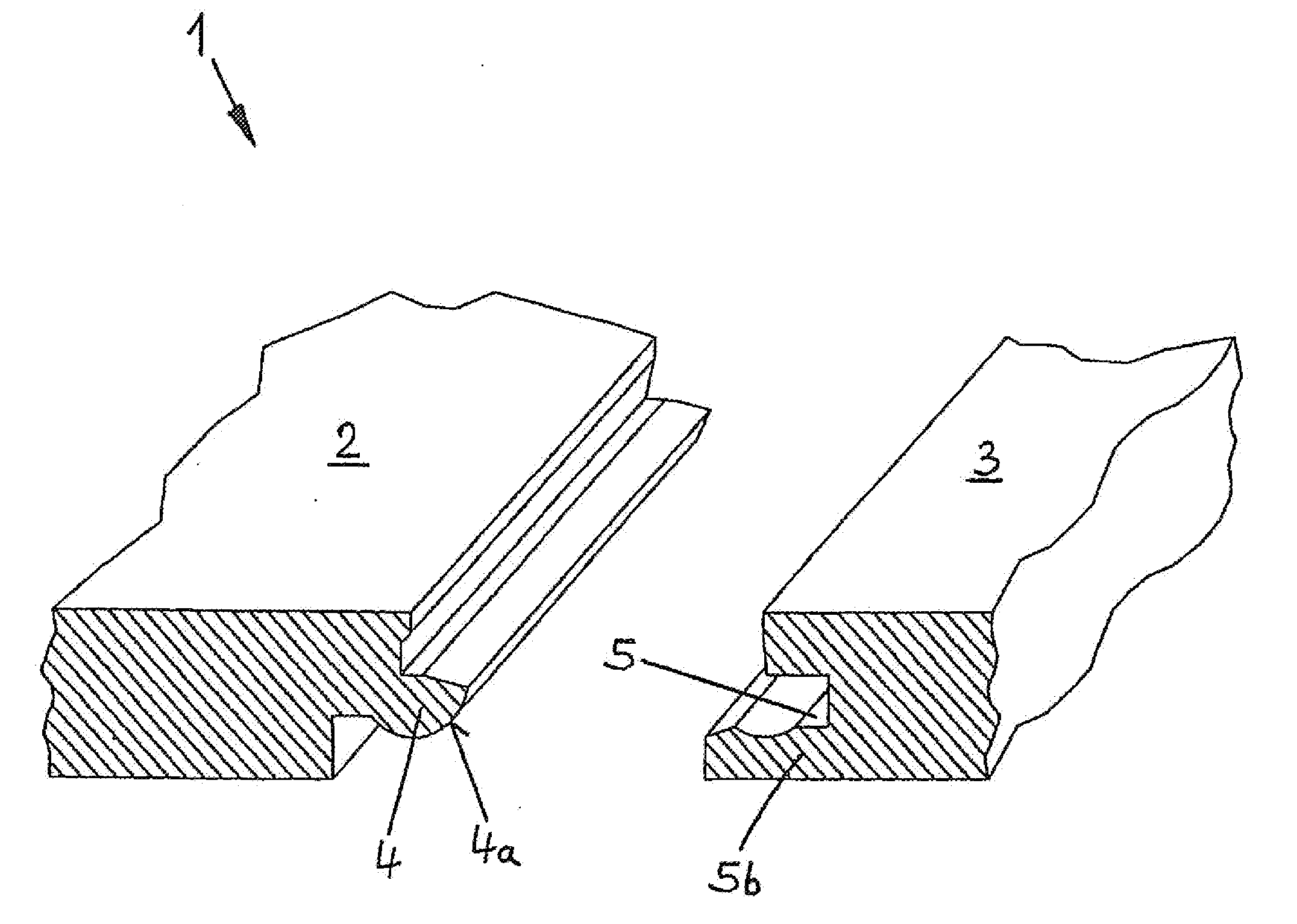
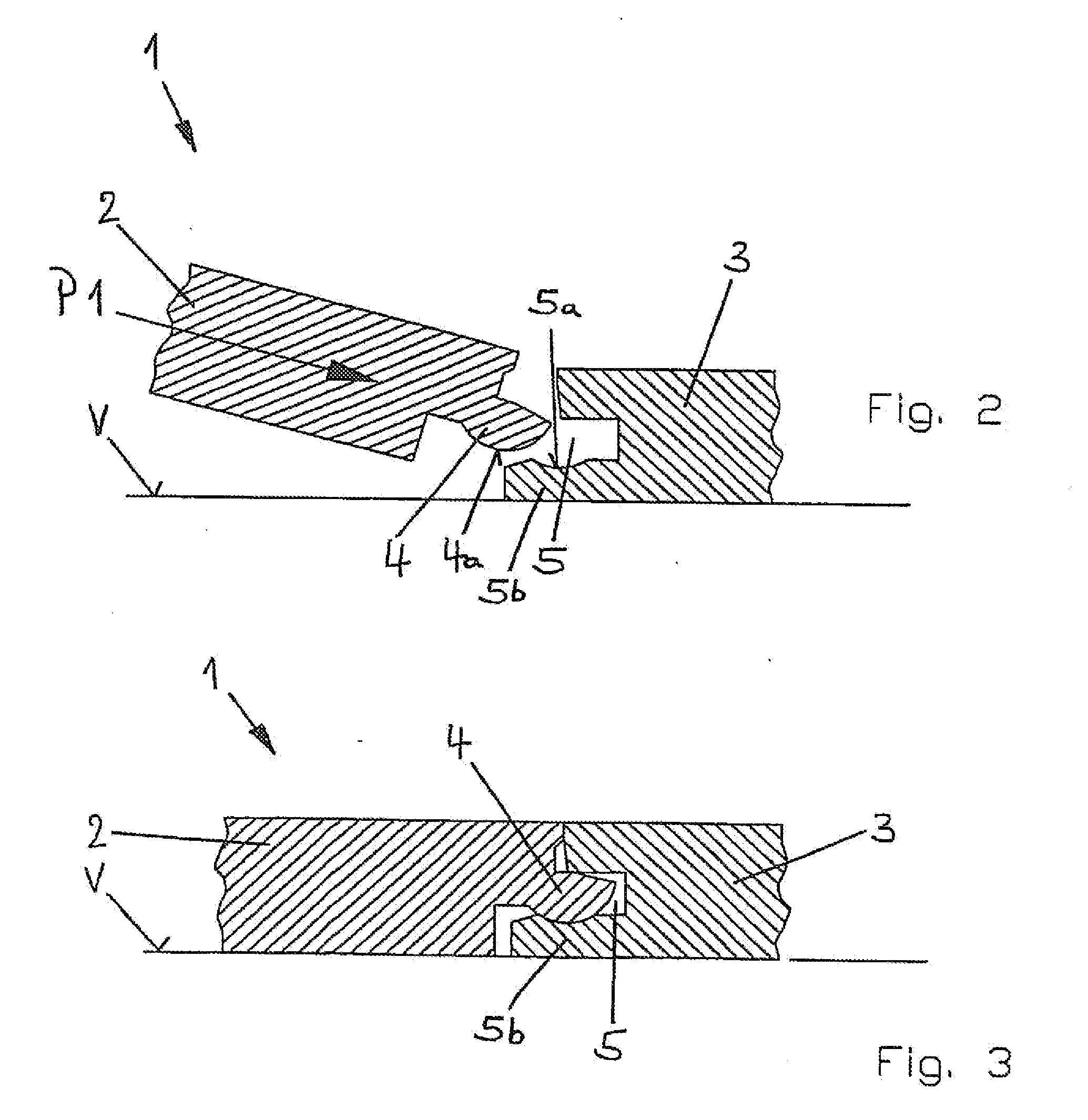
[0047]FIG. 1 of the drawing shows a perspective view of one type of retaining profile for fastening system 1 according to the invention. The opposite small faces of panels 2 and 3 are provided with corresponding retaining profiles, so that adjacent panels 2 and 3 can be connected to each other. This type of retaining profile is a modified tongue-and-groove joint, where tongue 4 engages an undercut in the lower groove wall of groove 5, so that, in the installed state, the two panels 2 and 3 are protected against being pulled apart in the plane of installed panels 2 and 3 and perpendicular to the direction of the: interlocked small faces.
[0048]FIG. 2 shows the attachment of a new panel 2 at an angle. In this context, tongue 4 of new panel 2 is always engaged with groove 5 of installed panel 3 in the direction of arrow P1, and new panel 2 is subsequently swiveled down onto base surface V until the position illustrated in FIG. 3 is reached. It is easily comprehensible that a curved are...
PUM
Abstract
The invention relates to a fastening system (1) for rectangular, tabular panels (2, 3, 10), especially floor panels. Comprising retaining profiles disposed on the small faces of said panels (2, 3, 10). Opposite retaining profiles match said retaining profiles in such a manner that similar panels (2, 3, 10) can be interlinked. The panels are provided with opposite first retaining profiles that are configured in such a manner that on a panel (2, 3, 10) being in first line a new panel (2) can be locked in second line by attaching the new panel (2) to the installed panel (3) at a temporary angle relative to the installed panel (3) and then swiveling it down into the plane of the installed panel (3). The panel further comprises opposite second retaining elements that comprise corresponding hook elements (6, 7). A hook connection (8) can be established by means of one of the hook elements (6, 7) of the new panel (2) and a hook element (6, 7) of a panel (3) that is already installed in second line by swiveling down the new panel (2). Every hook connection (8) is associated with an additional locking element (13, 22, 26, 27, 34, 35, 36, 40, 46) that prevents, in the hooked state of two panels (2, 3, 10), the book connection (8) from being released in a direction perpendicular to the plane of the installed panels (2, 3 10).
Description
BACKGROUND OF THE INVENTION [0001] 1. Field of the Invention [0002] The invention relates to a fastening system for rectangular, tabular panels, especially floor panels, comprising retaining profiles disposed on the small faces of said panels. Opposite retaining profiles match said retaining profiles in such a manner that similar panels can be interlinked. The retaining profiles are designed as first retaining profiles on opposite small faces and as second retaining profiles on the remaining small faces, in such a way that, on a panel in a first line, a new panel can be locked in a second line by attaching the new panel to the installed panel at a temporary angle relative to the installed panel and then swiveling it down into the plane of the installed panel, where the opposite second retaining elements display corresponding hook elements and where a hook connection can be established by means of one of the hook elements of the new panel and a hook element of a panel that is already...
Claims
Application Information
Patent Timeline
Application Date:The date an application was filed.
Publication Date:The date a patent or application was officially published.
First Publication Date:The earliest publication date of a patent with the same application number.
Issue Date:Publication date of the patent grant document.
PCT Entry Date:The Entry date of PCT National Phase.
Estimated Expiry Date:The statutory expiry date of a patent right according to the Patent Law, and it is the longest term of protection that the patent right can achieve without the termination of the patent right due to other reasons(Term extension factor has been taken into account ).
Invalid Date:Actual expiry date is based on effective date or publication date of legal transaction data of invalid patent.
Patent Type & Authority Applications(United States)