
Keyboard with illuminating architecture

a technology of illuminating architecture and keyboard, which is applied in the field of keys, can solve the problems of power consumption and heat production, power consumption and heat generation, and the total amount of components is much greater, and achieves the effects of reducing the required amount of leds, simplifying the number of whole components, and increasing the distance to the illuminator

Inactive Publication Date: 2012-05-22
ZIPPY TECH
View PDF33 Cites 47 Cited by
  • Summary
  • Abstract
  • Description
  • Claims
  • Application Information

AI Technical Summary

Benefits of technology

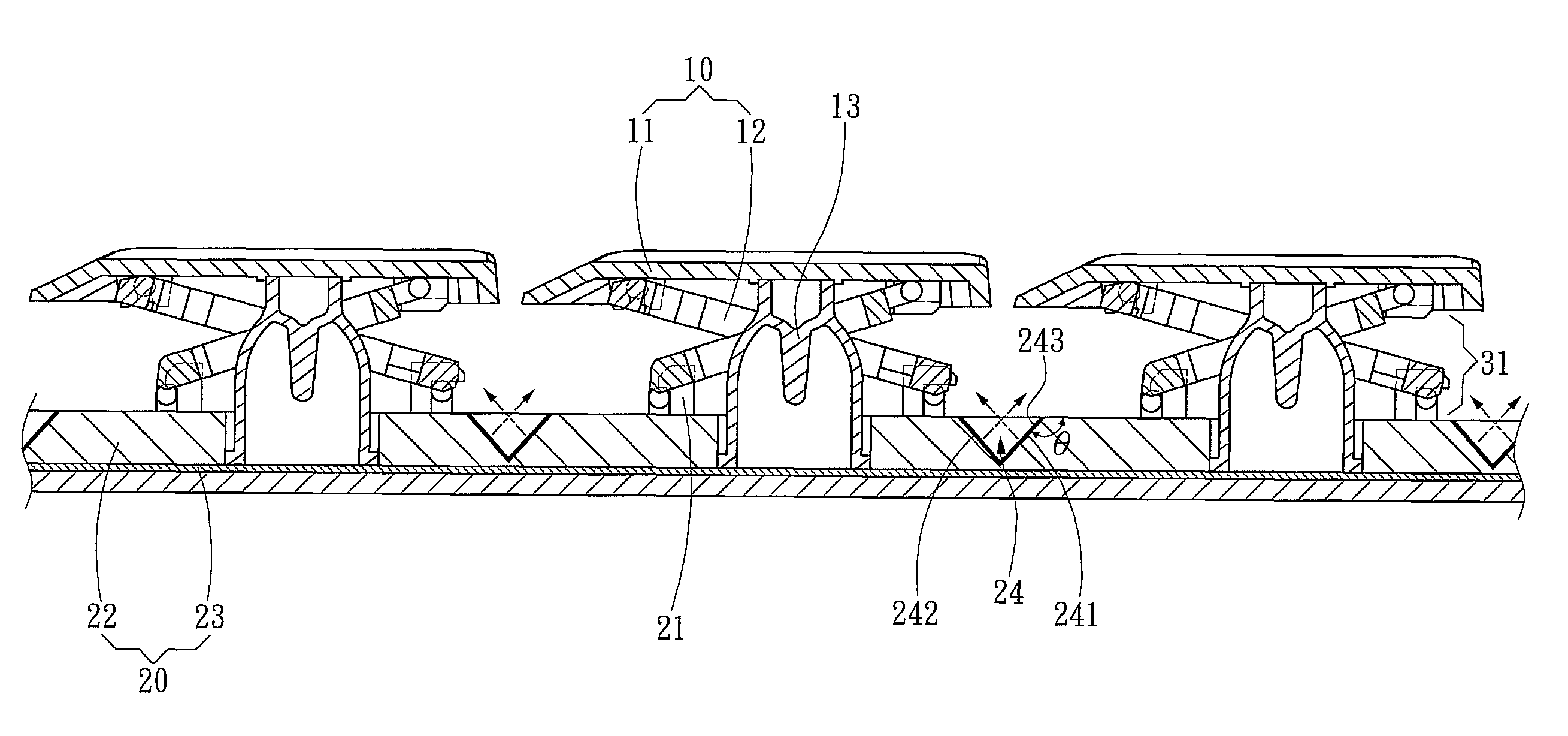
"The present invention provides a keyboard with illuminating architecture that simplifies the components and reduces the thickness of the keyboard. The keyboard includes a keyboard portion with inter-dependent mechanisms for providing a moving stroke of the pressing elements, and a substrate with a light guiding groove that reflects light to the keyboard portion for providing the pressing elements with brightness. The substrate also includes a plank for mounting the assembling portion and a circuit board triggered by the pressing elements for producing indicating signals. The light guiding groove can have a smooth slope or step structure mounted thereon to achieve uniform brightness between the pressing elements and the substrate. The present invention reduces the required amount of LEDs and simplifies the components, thereby achieving thinning of the keyboard."

Problems solved by technology

Although this kind of keyboard can prevent the incapability of recognizing the keys' positions in the dark, since the standard keyboard has more than one hundred keys and each key has to equip with the corresponding LED, the whole amount of components becomes much greater, the manufacturing process and cost are definitely increased and the weight even becomes larger.
Besides, the power consumption and heat production owing to the large amount of LEDs also might influence the user.

Method used


Image

  • Keyboard with illuminating architecture
  • Keyboard with illuminating architecture
  • Keyboard with illuminating architecture

Examples


Embodiment Construction

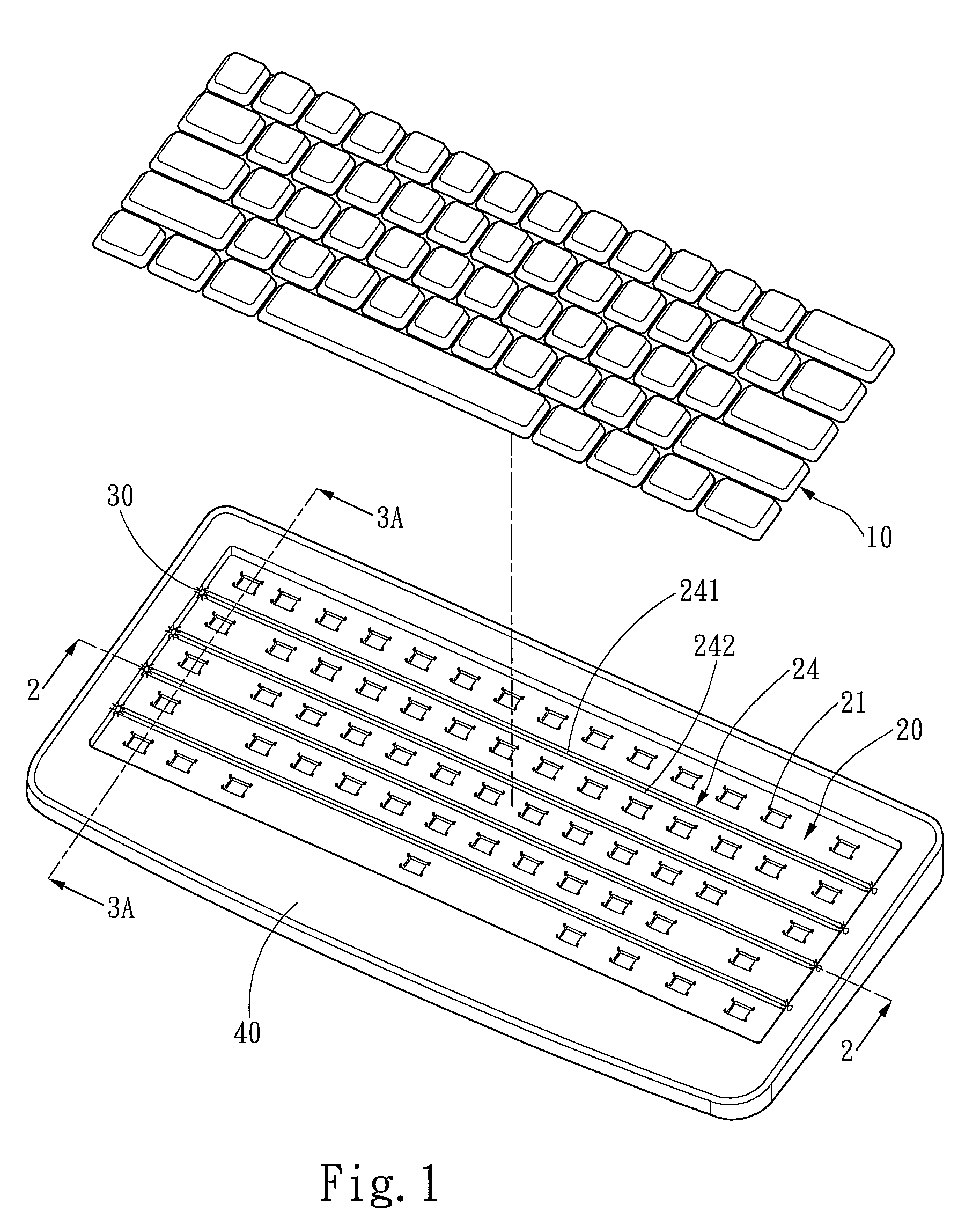
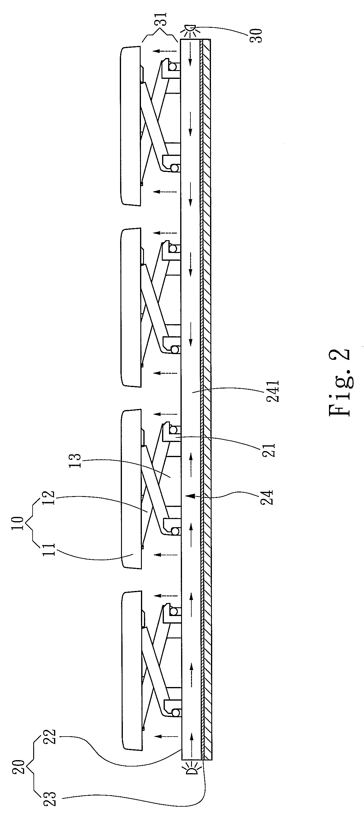
[0016]Please refer to FIG. 1, FIG. 2 and FIG. 3A, which respectively showing a partial decomposition drawing of a preferred embodiment, a sectional view of 2-2 line in FIG. 1 and a sectional view of 3A-3A line in FIG. 1. As shown, the present invention is related to a keyboard with illuminating architecture including a keyboard portion 10 in a housing 40 and a substrate 20, wherein the substrate 20 is used to carry the keyboard portion 10. The keyboard portion 10 includes a plurality of pressing elements 11 for receiving the pressing force from the user, and a plurality of inter-dependent mechanisms 12 under the force receiving surface of the pressing elements 11 for providing a moving stroke of the pressing elements 11 following the force direction. The inter-dependent mechanism 12 includes a flexible element 13 for providing the pressing element 11 the upward and downward movements. The substrate 20 has an assembling portion 21 for assembling with the other end of the inter-depend...


PUM


Abstract

A keyboard with illuminating architecture includes a keyboard portion and a substrate carrying the keyboard portion, wherein the keyboard portion includes a plurality of pressing elements for receiving a pressing force from the user and inter-dependent mechanisms respectively under a force receiving surface of each pressing element for providing a moving stroke of the pressing element following the force direction, and the substrate has an assembling portion for assembling with the other end of the inter-dependent mechanism. Moreover, the surface of the substrate has at least one light guiding groove, which forms a light channel for transmitting light, and at least one inner sidewall of the light guiding groove is a light reflecting surface, so that the light in the light guiding groove is reflected by the light reflecting surface to the keyboard portion, thereby providing the pressing elements the brightness, and reducing whole keyboard thickness and thinning.

Description

FIELD OF THE INVENTION[0001]The present invention is related to a keyboard, and more particularly to a keyboard with illuminating architecture.BACKGROUND OF THE INVENTION[0002]Since keyboard device is the main input device in computer system, it has to conform to different developments and using demands of computer system due to the diversification of using environment and timing. For providing the user the positions of each key in a dark environment, a keyboard with illuminating capability is developed, such as U.S. Pat. No. 5,936,554, U.S. Pat. No. 7,278,750, TWP No. 566612 and TWP No. 581961, which respectively disclose a keyboard device with LEDs (Light Emitting Diode) mounted therein and each LED provides light for a single key, so that the keys can be clearly recognized in the dark. Although this kind of keyboard can prevent the incapability of recognizing the keys' positions in the dark, since the standard keyboard has more than one hundred keys and each key has to equip with...

Claims


Application Information

Patent Timeline
Patent Type & Authority Patents(United States)
IPC IPC(8): H03K17/94
CPCH01H13/83H01H2219/044H01H2219/06H01H2219/062
Inventor CHOU, CHIN-WEN
Owner ZIPPY TECH
Learn More