Image recording apparatus

a technology for recording apparatuses and images, applied in the direction of thin material handling, article separation, transportation and packaging, etc., can solve the problems of inability to manufacture sheet-supply cassettes, inability to reduce so as to avoid the deterioration of recording quality, the effect of reducing the thickness of the apparatus

Inactive Publication Date: 2008-08-19
BROTHER KOGYO KK
View PDF24 Cites 40 Cited by
  • Summary
  • Abstract
  • Description
  • Claims
  • Application Information

AI Technical Summary

Benefits of technology

[0010]In the meantime, in the image recording apparatus configured such that the sheet-discharge portion is disposed above the sheet-supply portion as disclosed in the above-indicated Patent Document 4, there have been recently made attempts to reduce the size, especially the thickness of the image recording apparatus. For this end, it is attempted to simplify the structures of the sheet-supply tray and the sheet-discharge tray by simplifying components to be used or permitting one component to have a plurality of functions, for satisfying a demand of reducing the overall size or the thickness of the apparatus and accordingly decreasing the cost of its manufacture.
[0012]To solve the problems described above with respect to the Patent Documents 1 and 2, it is an object to provide an image recording apparatus which is capable of reliably supplying recording media to an image recording portion with a small-sized and simplified structure without attaching additional components to a cassette for supplying the media, which is arranged to prevent interference between the cassette and a sheet-feed roller upon insertion and removal of the cassette into and from the apparatus, and which assures easy assembling and a reduced cost of its manufacture.
[0013]To solve the problems described above with respect to the Patent Documents 3 and 4, it is an object to provide an image recording apparatus and a sheet-supply tray which assures a reduced size of the apparatus as a whole and avoids feeding failures of the recording media while simplifying structures of a sheet-supply tray and a sheet-discharge tray.
[0018]In the image recording apparatus and the sheet-supply cassette constructed as described above, the auxiliary sheet-discharge tray as a supplement of the sheet-discharge tray is attached to the sheet-supply tray which is located below the sheet-discharge tray and a clearance between the sheet-discharge tray and the sheet-supply tray is effectively utilized as a space for permitting the movement of the auxiliary sheet-discharge tray between the tray-accommodated position and the tray-extended position. Accordingly, the auxiliary sheet-discharge tray which cooperates with the sheet-discharge tray to support the recording sheets with high stability can be provided without giving any hindrance to the reduction of the thickness of the apparatus as a whole.
[0019]Because the auxiliary sheet-discharge tray is arranged to be movable between the tray-extended position and the tray-accommodated position, it can be placed at the tray-accommodated position when it is not used, for preventing the auxiliary sheet-discharge tray from disturbing the supply of the recording sheets to the sheet-supply tray.
[0020]The first accommodating portion formed in the sheet-supply tray so as to have the recessed shape for accommodating the auxiliary sheet-discharge tray is provided with the flexure-preventive portion for preventing the recording sheets from being deflected downwards. Therefore, this arrangement prevents the recording sheets from remaining deflected, for instance, so that feeding failures and the deterioration of the recording quality can be avoided.

Problems solved by technology

Therefore, the sheet-supply cassette undesirably has a width dimension larger than a maximum width dimension of the recording sheets that can be accommodated in the sheet-supply cassette.
Therefore, the apparatus tends to be large-sized and have a relatively large height dimension.
Thus, the manufacture of the sheet-supply cassette inevitably becomes cumbersome.
Accordingly, where the recessed surface of the accommodating portion is exposed when the auxiliary tray is placed in its extended portion, there may occur a phenomenon that the recording sheets accommodated in the sheet-discharge tray suffer from flexure such that the recording sheets partially drop downwards onto the recessed surface of the accommodating portion.
If the recording sheets deflect or remain deflected, there may be caused the following feeding failures of the sheets: A plural sheets may be fed at one time by a sheet-supply means without being separated from one another or the sheets may be creased or jammed while being fed in the sheet-feed path.
Moreover, where a recording head of an ink-jet type is used in the image recording unit of the apparatus, the flexure of the sheets may cause differences in the distance between the recording head and the surface of the sheets to be recorded, at local portions on the surface of the sheets, undesirably deteriorating the recording quality.

Method used


Image

  • Image recording apparatus
  • Image recording apparatus
  • Image recording apparatus

Examples


Embodiment Construction

[0044]Referring to the drawings, there will be explained an image recording apparatus to which are applied claimable inventions.

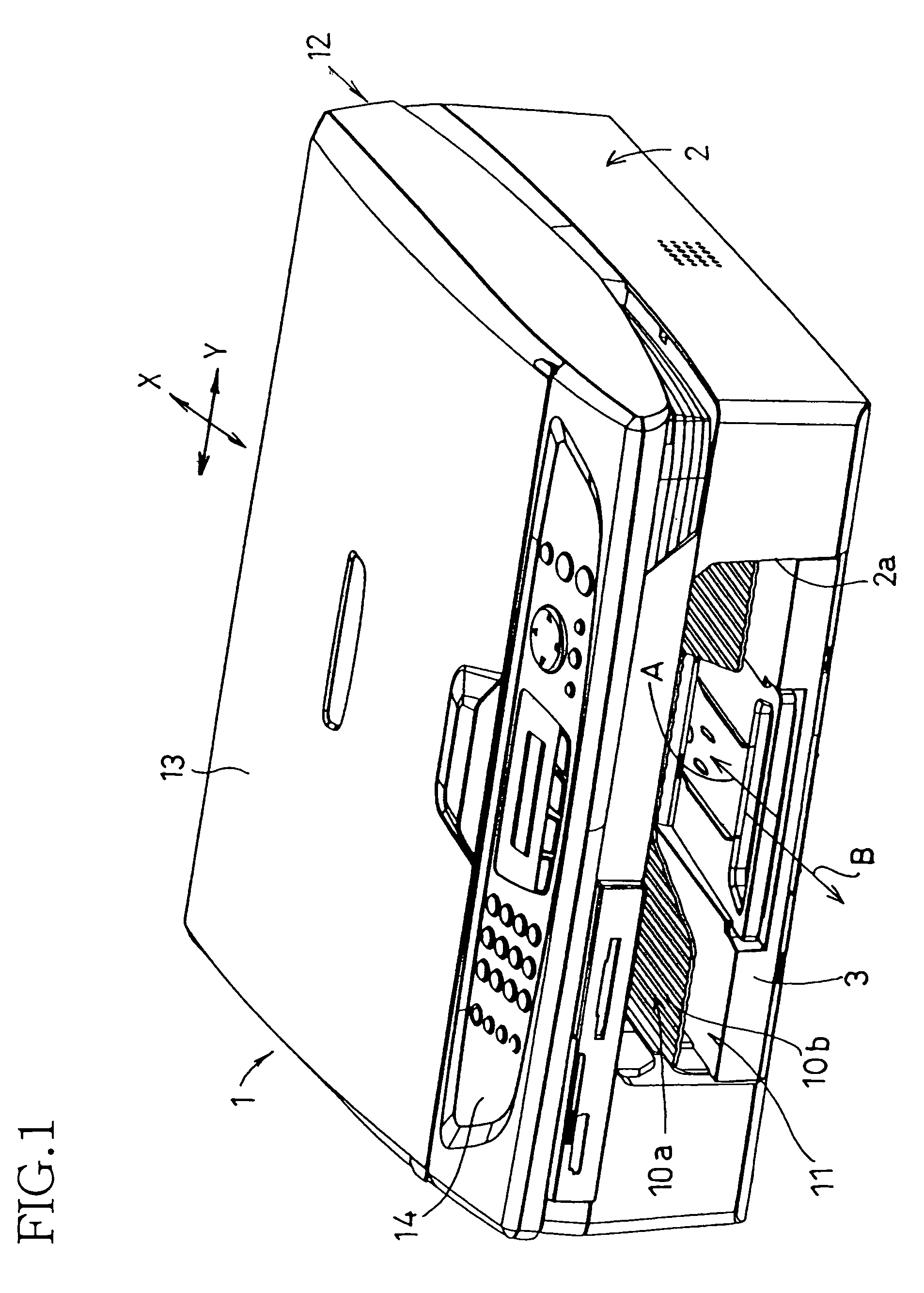
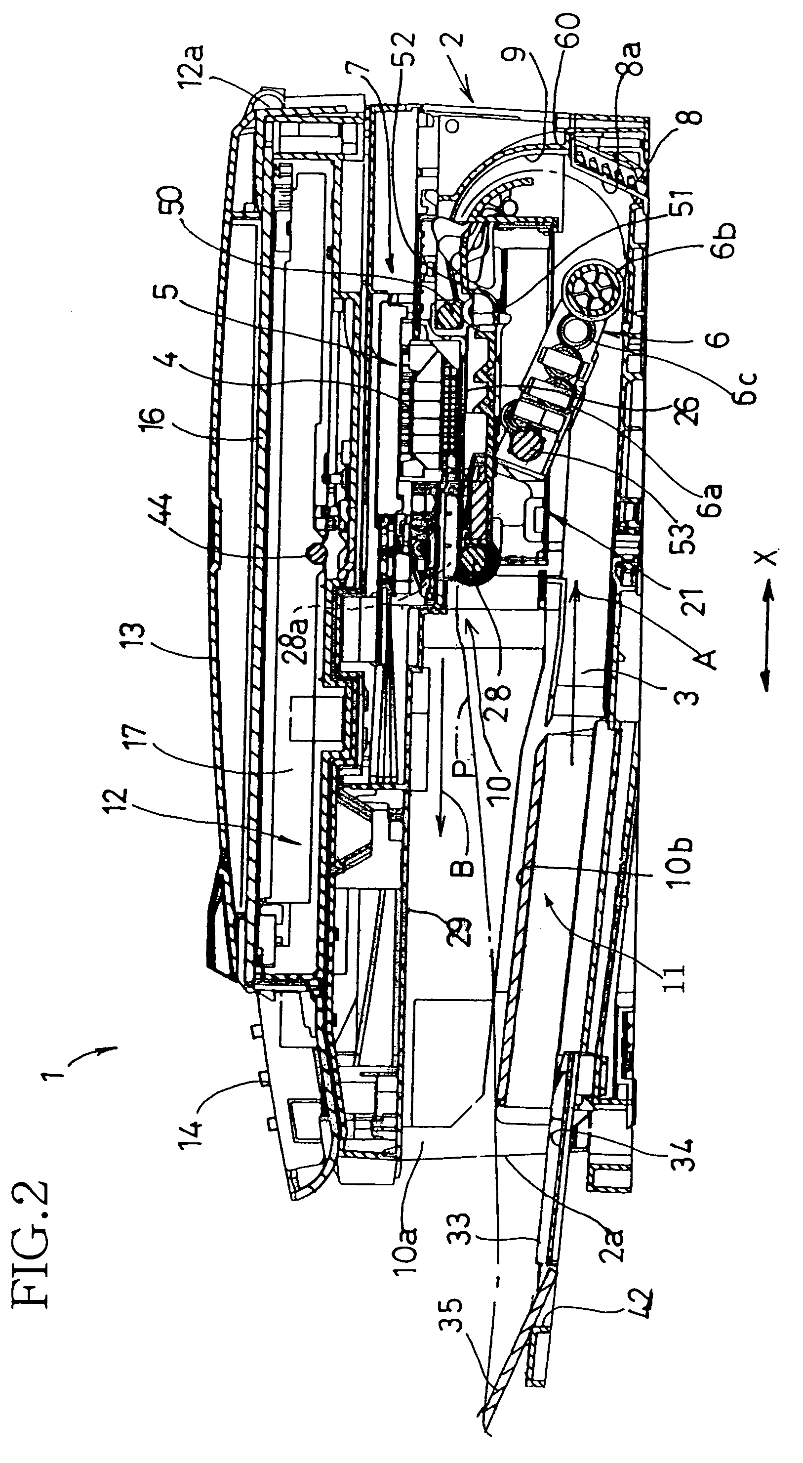
[0045]FIGS. 1 and 2 show the image recording apparatus 1 in the form of a multi-function device (MFD) which has a printing function, a copying function, a scanning function and a facsimile function. As shown in FIGS. 1 and 2, the image recording apparatus 1 has a housing 2 as a main body of the apparatus. The housing 2 is formed by injection-molding of a synthetic resin material.

[0046]On an upper portion of the housing 2, there is disposed an image reading device 12 which operates in the copying function and the facsimile function of the apparatus 1. The image reading device 12 is arranged to be pivotable upwards and downwards about one end of the housing 2 via a hinge device not shown. An original covering member 13 covering an upper surface of the image reading device 12 is pivotally connected at its rear end to a rear end of the image reading device 12 t...


PUM


Abstract

An image recording apparatus including: a sheet-supply cassette which accommodates a stack of recording sheets and which is insertable into and removable from a main body of the apparatus; an end wall which is disposed at a downstream end of the cassette in a sheet-supply direction in which the sheets are supplied, so as to extend in a direction perpendicular to the sheet-supply direction and which has a height larger than that of a maximum number of the sheets that can be accommodated in the cassette; an image recording unit disposed in the main body for recording an image on the sheets; an arm disposed in the main body and pivotable about a shaft which extends in the direction perpendicular to the sheet-supply direction; a sheet-feed roller which is disposed at a free end of the arm and which is, in a state in which the cassette is inserted into the main body, in contact with an uppermost one of the sheets accommodated in the cassette and which feeds the uppermost one of the sheets toward the image recording unit; and a link mechanism which is disposed in the main body for raising and lowering the roller and the arm and which cooperates with the end wall to retract the roller and the arm above the cassette when the cassette is inserted into and removed from the main body.

Description

[0001]The present application is based on Japanese Patent Application Nos. 2004-268861 filed on Sep. 15, 2004 and 2004-376506 filed on Dec. 27, 2004, the contents of which are incorporated herein by reference.BACKGROUND OF THE INVENTION[0002]1. Field of the Invention[0003]Claimable inventions relate in general to an improved structure of an image recording apparatus.[0004]2. Discussion of Related Art[0005]In an image recording apparatus such as a printer, a copying machine, a facsimile machine or the like, there is provided a structure which prevents a sheet-feed roller from interfering with a sheet-supply cassette when the sheet-supply cassette is inserted into or removed from the apparatus. For instance, Patent Document 1 (JP-A-2002-249242, in particular FIGS. 3-8) and Patent Document 2 (U.S. Pat. No. 6,651,974 corresponding to JP-A-2002-321838, in particular FIGS. 4-9) disclose one example of such a structure. Namely, guide surfaces are respectively formed on upper surfaces of si...

Claims


Application Information

Patent Timeline
Patent Type & Authority Patents(United States)
IPC IPC(8): B65H3/06
CPCB65H3/56B65H3/0684
Inventor ASADA, TETSUOTAKEMOTO, TAKATOSHI
Owner BROTHER KOGYO KK
Why Eureka
Try Eureka