Motor-driven actuator

a motor-driven actuator and actuator technology, applied in the direction of dynamo-electric components, gearing, dynamo-electric machines, etc., can solve the problems of wear, vibration, corrosion, etc., to detect the full extension and full retraction in order to terminate the current flow to the electric motor, and the effect of reducing the wear resistan

Inactive Publication Date: 2008-01-17
THERMOTION ACQUISITION
View PDF12 Cites 12 Cited by
  • Summary
  • Abstract
  • Description
  • Claims
  • Application Information

AI Technical Summary

Benefits of technology

The invention is an actuator that uses a position detector to detect when the piston rod is extended or retracted. The detector includes Hall effect sensors and a permanent magnet mounted on the piston. This detector does not use sliding contacts, which can cause wear, vibration, corrosion, and contamination. The technical effect of this invention is to provide a reliable and durable actuator that can detect its position accurately without the need for sliding contacts.

Problems solved by technology

The technical problem addressed in this patent text is the lack of flexibility and the use of a sliding electrical contact to detect the full extension and full retraction of the piston rod, which can result in wear, vibration, and corrosion.

Method used


Image

  • Motor-driven actuator
  • Motor-driven actuator
  • Motor-driven actuator

Examples


Embodiment Construction

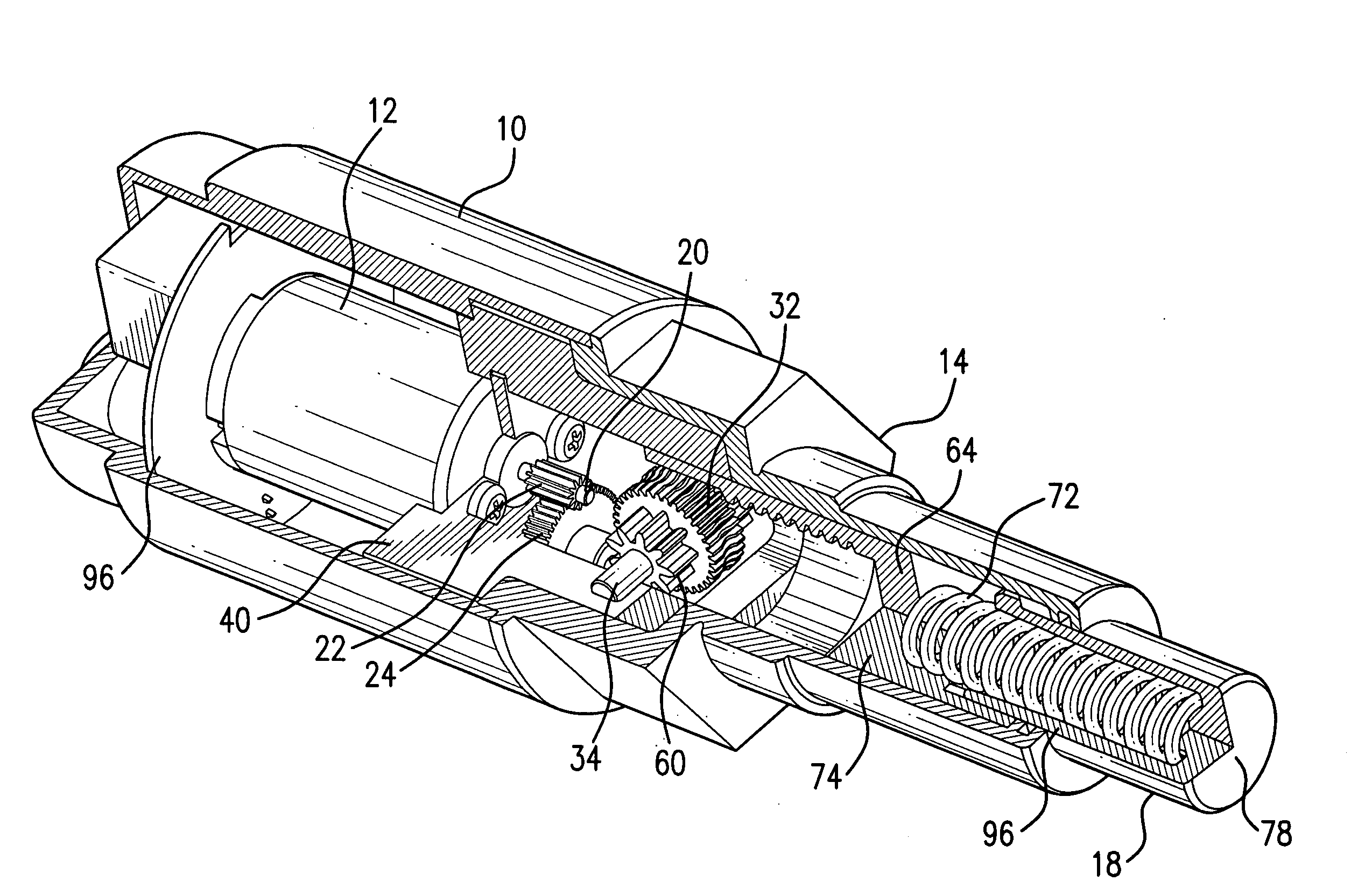
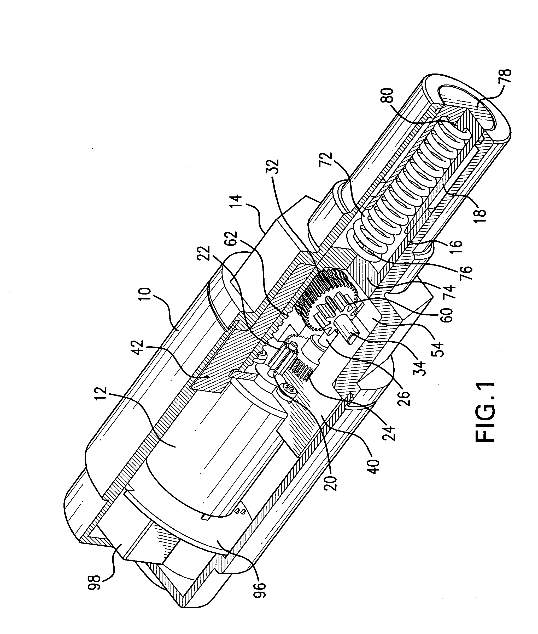
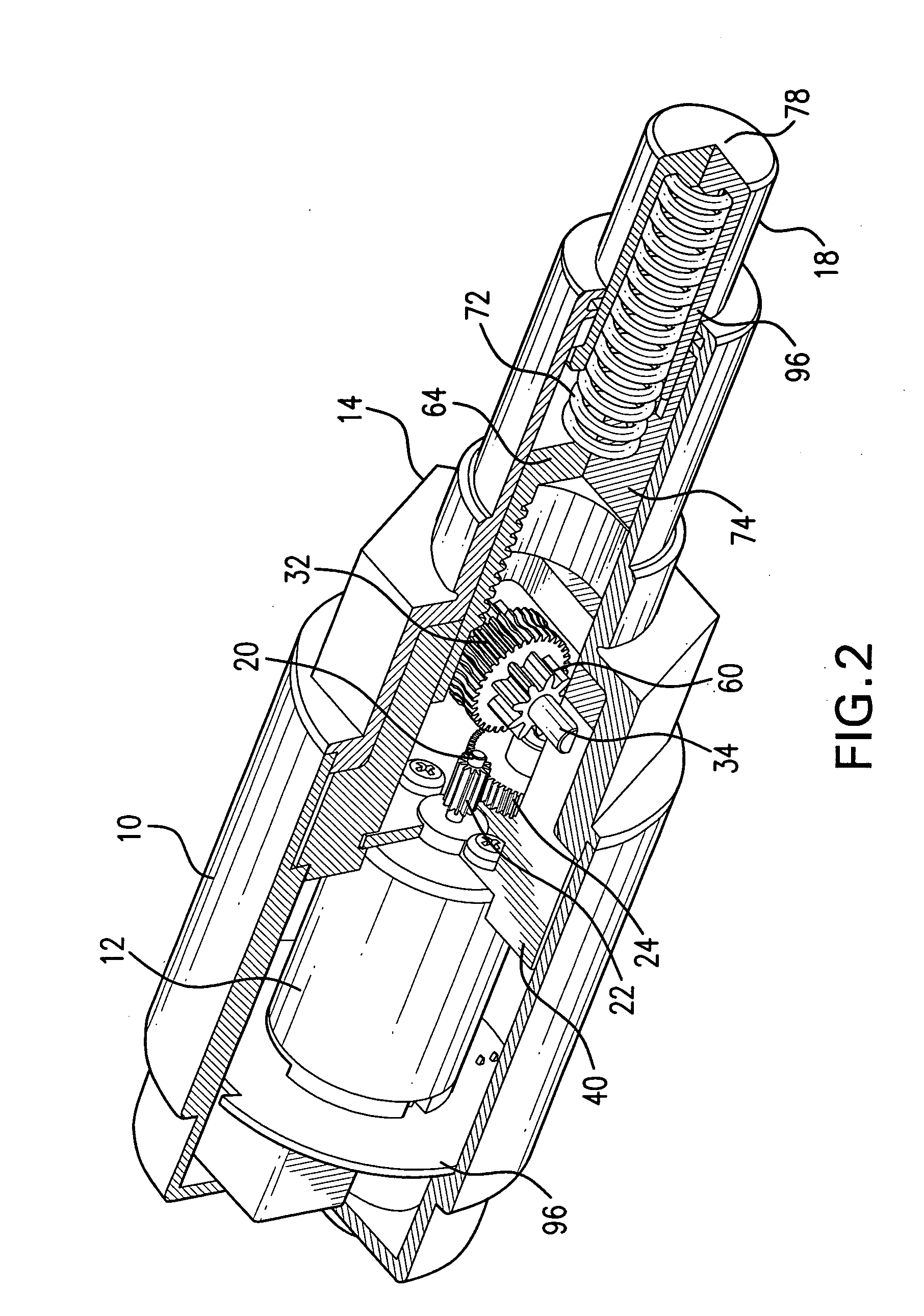
[0015]An embodiment of a motor-driven actuator according to the invention is illustrated in FIGS. 1, 3A, 3B, and 6 and some parts of that actuator are illustrated in FIGS. 3C, 4A, 4B, 5A, and 5B. The actuator includes an external housing having a rear part 10 containing an electric motor 12. A front part 14 of the external housing is joined to the rear part 10 and contains, among other parts, a piston 16 and a piston rod 18 that may be extended from and retract into the front part 14 of the housing. Typically, the electrical motor 12 is a direct current motor that can be reversed in the direction of rotation of a shaft 20 by reversing the polarity of an electrical current supplied to the motor. Preferably, the rear part housing 10 includes, opposite the motor 12, internal surfaces complementary to the external shape of the motor 12. The rear part housing 10 holds the motor and the remainder of the internal parts of the actuator, described below, in place within the actuator. Most pr...


PUM


Abstract

A motor-driven actuator extends and retracts a piston rod. The actuator includes a housing, an electric motor having a motor shaft, a piston rod slidably extendable and retractable with respect to the housing, a speed-reduction stage coupled to the motor shaft and rotating a drive shaft parallel to the motor shaft, a speed and direction-change stage coupled to and driven by the drive shaft and rotating a wheel gear substantially perpendicular to the motor shaft, and a driving stage coupled to and driven by the wheel gear and extending and retracting the piston rod relative to the housing along a direction parallel to the motor shaft. The actuator also includes a position detector detecting when the piston rod is in the extended and retracted positions. Preferably, the position detector includes Hall effect sensors and a permanent magnet mounted on a piston driving the piston rod.

Description


Claims


Application Information

Patent Timeline
Owner THERMOTION ACQUISITION
Why Eureka
Try Eureka