
Selectively actuated constant flow valve

Active Publication Date: 2008-01-17
GLOBAL AGRI TECH & ENG
View PDF4 Cites 28 Cited by
  • Summary
  • Abstract
  • Description
  • Claims
  • Application Information

AI Technical Summary

Benefits of technology

[0007] In accordance with still another aspect of the present invention, the vent opening communicating with the valve's spring chamber is provided with a seal which allows air to escape and enter the spring chamber, but which prevents the escape of liquid from the spring chamber in the event that the valve diaphragm is breached.
[0008] In accordance with another aspect of the present invention, a pressure relief mechanism is provided for relieving residual fluid inlet pressure below the threshold level when the valve is closed.

Problems solved by technology

However, at fluid inlet pressures above the threshold level, such valves remain open and cannot serve as shut off valves, thus making it necessary to employ additional and separately operable valves to achieve this added function.

Method used


Image

  • Selectively actuated constant flow valve
  • Selectively actuated constant flow valve
  • Selectively actuated constant flow valve

Examples


Embodiment Construction

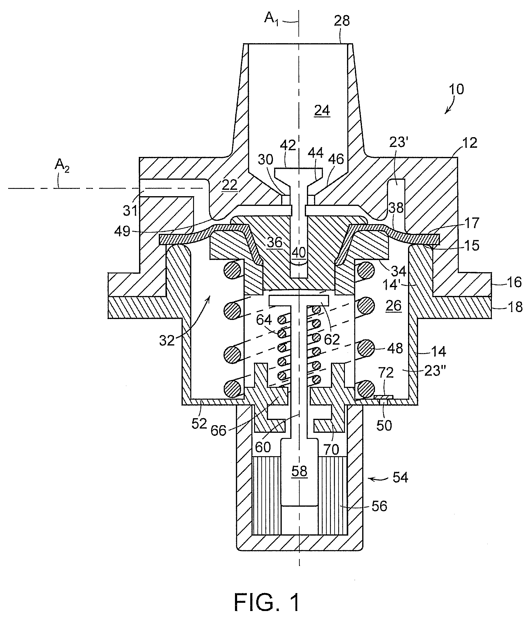
[0024] With reference initially to FIG. 1, a regulating valve in accordance with the present invention is generally depicted at 10. The valve includes an outer housing having a cap 12 joined to a cup-shaped base 14 at mating exterior flanges 16, 18.

[0025] The housing is internally subdivided by a barrier wall 22 into a head section 24 and a base section 26. An inlet 28 in the cap 12 is adapted to be connected to a fluid supply (not shown) having a pressure that can vary from below to above a threshold level. The inlet 28 and a central port 30 in the barrier wall 22 are preferably aligned coaxially with a central axis A1 of the valve. An outlet port 31 is provided in the cap 12, and may be aligned on a second axis A2 transverse to the first axis A1. Although the axis A2 is shown at 90° with respect to axis A1, it will be understood that axis A2 may be oriented at other angles with respect to axis A1 in order to suit various applications of the valve.

[0026] A modulating assembly 32 ...


PUM


Abstract

A constant flow regulating valve of the type described in U.S. Pat. Nos. 6,026,850 and 6,209,578 includes a closure mechanism configured and arranged to override the modulating mode of the valve and to close the valve at fluid inlet pressures both below and above the valve's threshold level. The closure mechanism may be selectively deactivated to thereby allow the valve to assume its normal pressure responsive regulating functions. Embodiments of the regulating valve incorporate pressure relief devices and vent seals, with configurations suitable for incorporation into the trigger assemblies of portable sprayers.

Description

CROSS REFERENCE TO RELATED APPLICATIONS [0001] This application is a continuation-in-part of U.S. Ser. No. 11 / 769,315 filed Jun. 27, 2007, which claims priority from provisional Patent Application Ser. Nos. 60 / 830,265 and 60 / 838,618 filed respectively on Jul. 12, 2006 and Aug. 23, 2006, and from Ser. No. 11 / 841,194 filed Aug. 20, 2007. This application claims priority from provisional application Ser. No. 60 / 888,621 filed Feb. 07, 2007.BACKGROUND OF THE INVENTION [0002] 1. Field of the Invention [0003] This invention relates generally to fluid valves, and is concerned in particular with a regulating valve that operates in response to a variable fluid inlet pressure above a selected threshold level to deliver the fluid at a constant outlet pressure and flow rate. A closure mechanism is selectively operable either to accommodate the valve's normal pressure responsive regulating functions, or to override such functions by maintaining the valve in a closed state at inlet pressures both ...

Claims


Application Information

Patent Timeline
Patent Type & Authority Applications(United States)
IPC IPC(8): F16K17/04
CPCB05B1/3013G05D16/0658F16K41/12Y10T137/7504Y10T137/7782Y10T137/7825Y10T137/7929
Inventor NEWTON, JOHN R.BROOKE, PETER J.
Owner GLOBAL AGRI TECH & ENG
Features
  • Generate Ideas
  • Intellectual Property
  • Life Sciences
  • Materials
  • Tech Scout
  • Unparalleled Data Quality
  • Higher Quality Content
  • 60% Fewer Hallucinations
Learn More