Cultivator and blade

a cultivator and blade technology, applied in the field of cultivators, can solve the problems of not being suitable for use with smaller plots or gardens, the arrangement of the tiller blades of marshall has a tendency to wander, and the implements employing riding vehicles

Inactive Publication Date: 2008-01-17
CATLIN BRUCE LEON
View PDF20 Cites 9 Cited by
  • Summary
  • Abstract
  • Description
  • Claims
  • Application Information

AI Technical Summary

Problems solved by technology

These manual tools require a user to rotate the tool prongs to till the soil and are of limited use for smaller plots.
Marshall's tiller blade arrangement has a tendency to wander when in use and consequently requires directional control assistance from a handle.
Other farm tiller implements employing riding vehicles are known, but are not suitable for use with smaller plots or gardens.

Method used


Image

  • Cultivator and blade
  • Cultivator and blade
  • Cultivator and blade

Examples


Embodiment Construction

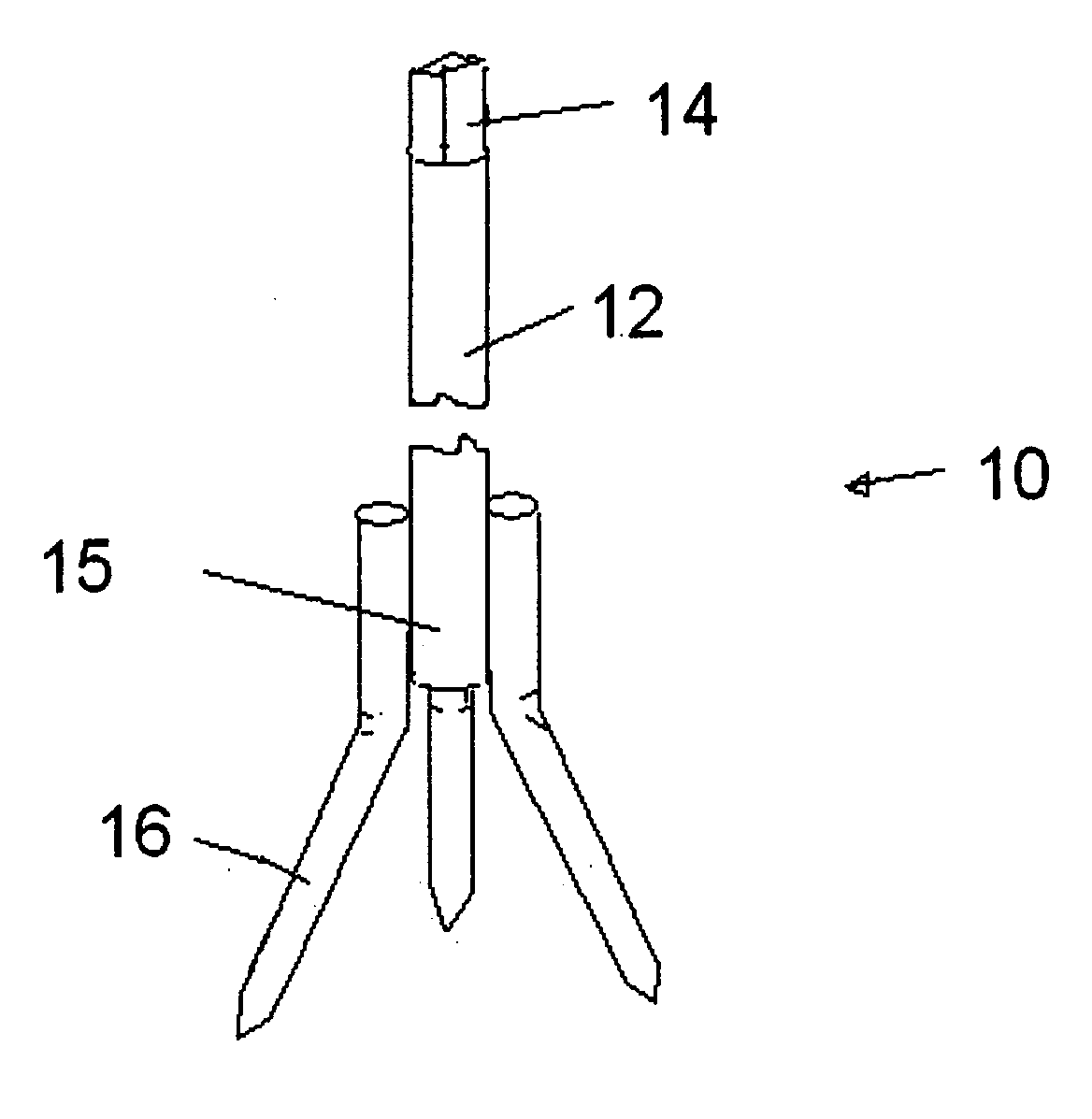
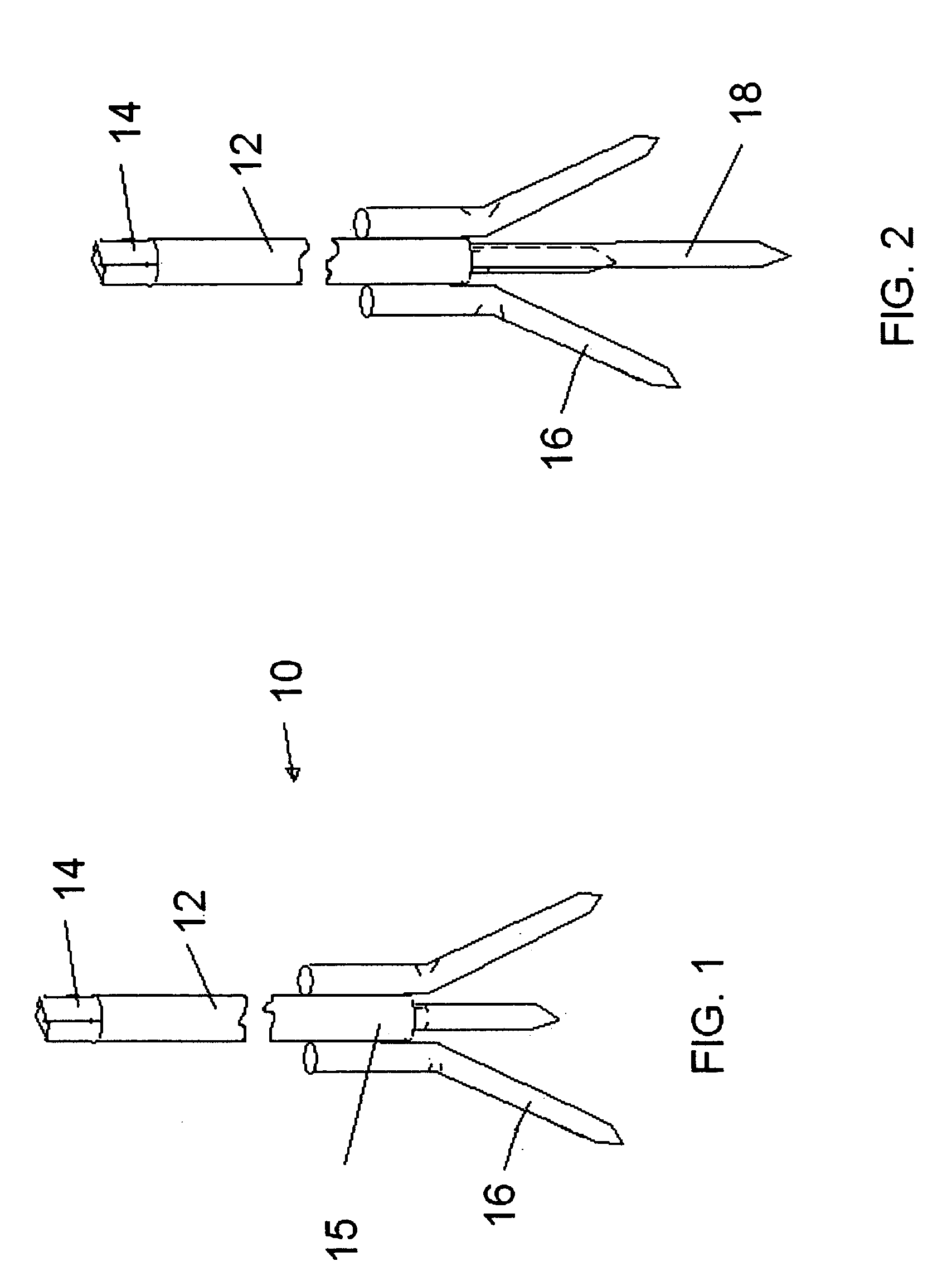
[0039]FIG. 1 is a perspective view of the simplest embodiment of the invention 10. It has a cylindrical shaft 12 with a round / square attachment end 14 adapted to fit within the chuck of a conventional power drill. The shaft 12 cultivating end 15 has three blades 16 attached and equally spread apart. The invention 10 is made of steel with the blades made of bent 60 penny gauge nails or tubular metal welded to the cultivating end 15 of the shaft 12 such that the blades 16 can be bent inwardly or outwardly, if desired to till different soils.

[0040]FIG. 2 is a perspective view of the embodiment shown in FIG. 1 with a vertical stabilizer 18, which acts as a center drill to prevent the attachment from drifting while in use.

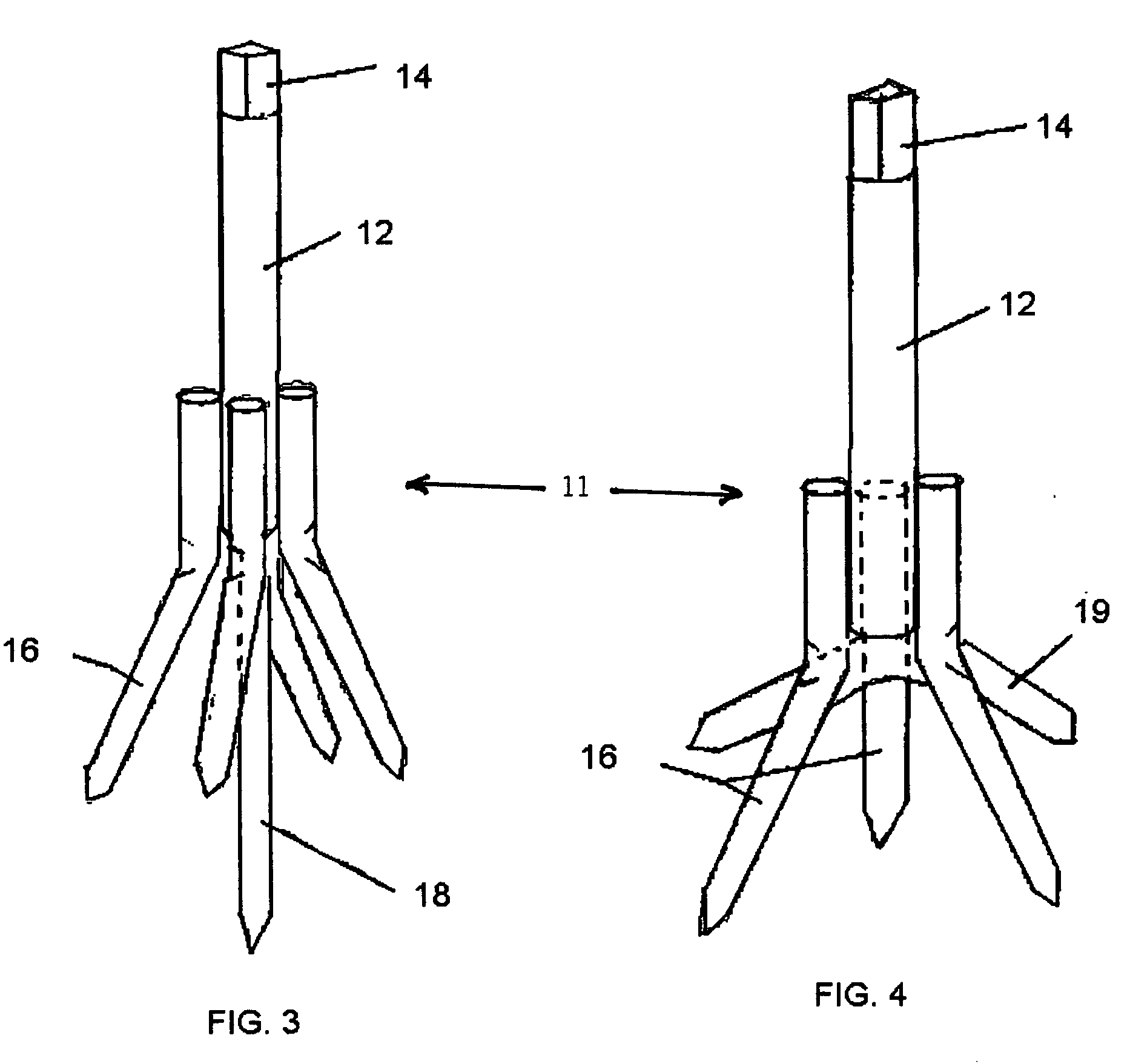
[0041]FIG. 3 is a perspective view of a four blade 16 cultivating blade attachment 10 with a vertical stabilizer 18. This embodiment provides superior cultivation when used in a vertical direction.

[0042]FIG. 4 is a perspective view of a three blade 16 cultivating blade ...


PUM


Abstract

An improved cultivator and blade attachment particularly suited for use with smaller ground plots and provides the advantages of an improved tiller blade design, which can be used laterally as well as horizontally to minimize blade migration.

Description

RELATED APPLICATIONS[0001]This application is a continuation-in-part patent application of the patent application entitled “Power Drill Cultivator Attachment” filed Jul. 12, 2006 and assigned Ser. No. 11 / 485,056BACKGROUND OF THE INVENTION[0002]1. Field[0003]This invention pertains to cultivators. More particularly, it relates to a cultivator and cultivator attachment for manual or rotary powered drive.[0004]2. State of the Art[0005]A number of cultivators are known. Hound Dog® Products, Inc. of Eden Prairie, Minn. produces a number of hand powered hand tool cultivators, such as its three pronged Mini-Tiller, and its six pronged Garden Hound® Tiller. These manual tools require a user to rotate the tool prongs to till the soil and are of limited use for smaller plots. Faultless Starch / Bon Ami® Company of Kansas City, Mo. also produces a similar line of hand cultivators, such as its Garden Claw™.[0006]Other powered cultivators such as Howard, U.S. Pat. No. 5,810,093 issued Sep. 22, 199...

Claims


Application Information

Patent Timeline
Patent Type & Authority Applications(United States)
IPC IPC(8): A01B13/08
CPCA01B1/065
Inventor CATLIN, BRUCE LEON
Owner CATLIN BRUCE LEON
Why Eureka
Try Eureka