Seat back structure of vehicle seat

a vehicle seat and seat back technology, applied in vehicle components, pedestrian/occupant safety arrangements, vehicle arrangements, etc., can solve the problems of not reaching the foregoing, the seat occupant's dorsal part might be damaged, and the headrest cannot be retained, so as to improve the seat back structure of the vehicle seat and avoid an excessive impact

Inactive Publication Date: 2008-01-17
TACHI S CO LTD
View PDF12 Cites 26 Cited by
  • Summary
  • Abstract
  • Description
  • Claims
  • Application Information

AI Technical Summary

Benefits of technology

The goal of this invention is to improve the safety of car seats that have a headrest. It was designed to reduce the risk of injury for drivers or passengers who are hit from behind during a crash. This new design helps distribute the force evenly across the entire body, reducing damage to the spine. Additionally, when there is a heavy load on the driver or passenger's shoulders, the headrest will still move forward, keeping them protected.

Problems solved by technology

The technical problem addressed in this patent is how to design an emergency active headrest system for vehicles that prevents damage to the occupant's brain during a rear-end collision without causing unstable loads on their body parts. More specifically, there is concern about ensuring proper placement of the headrest relative to the occupant's head and maintaining stability through continuous application of a biasing force.

Method used


Image

  • Seat back structure of vehicle seat
  • Seat back structure of vehicle seat
  • Seat back structure of vehicle seat

Examples


Embodiment Construction

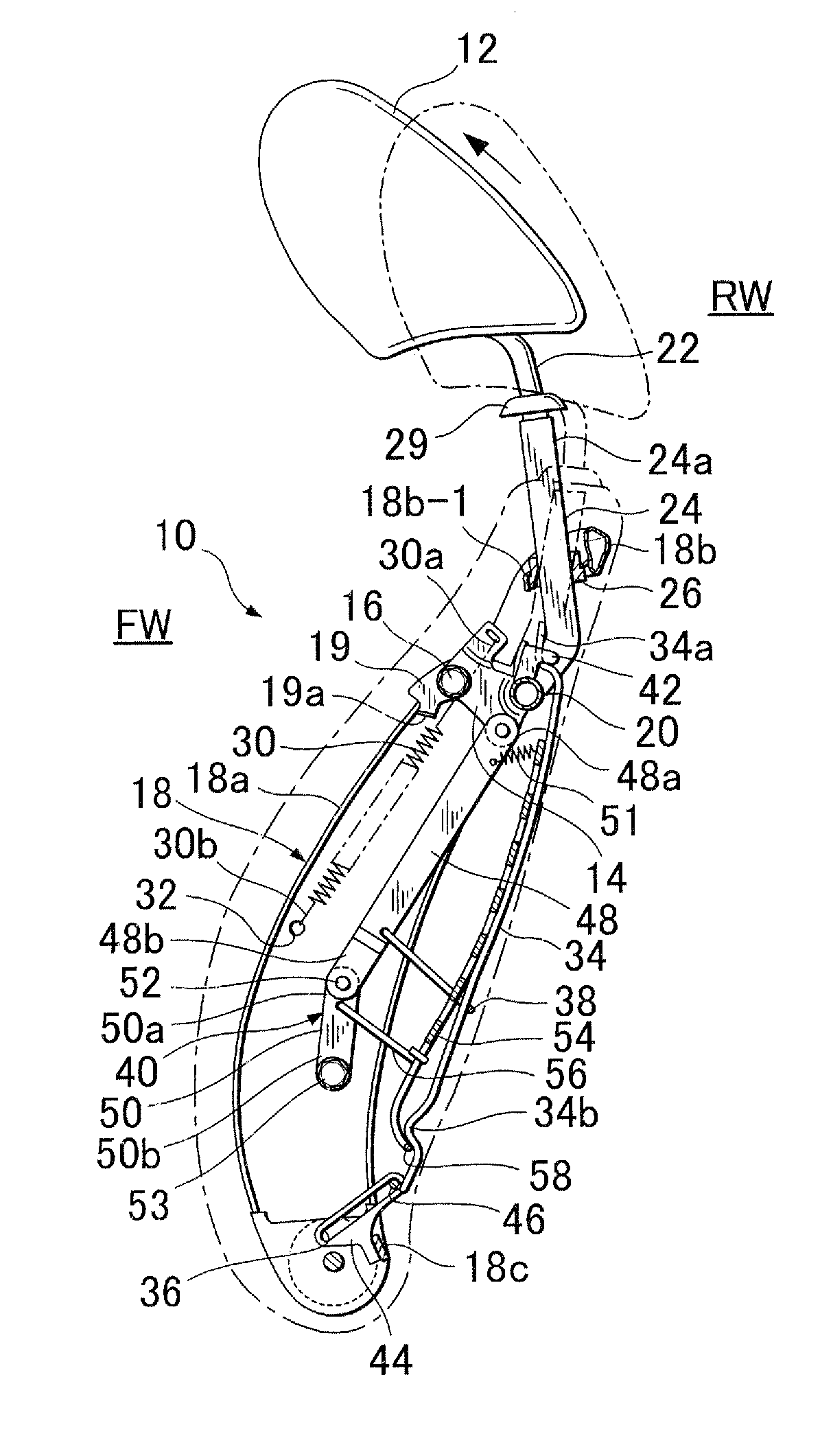
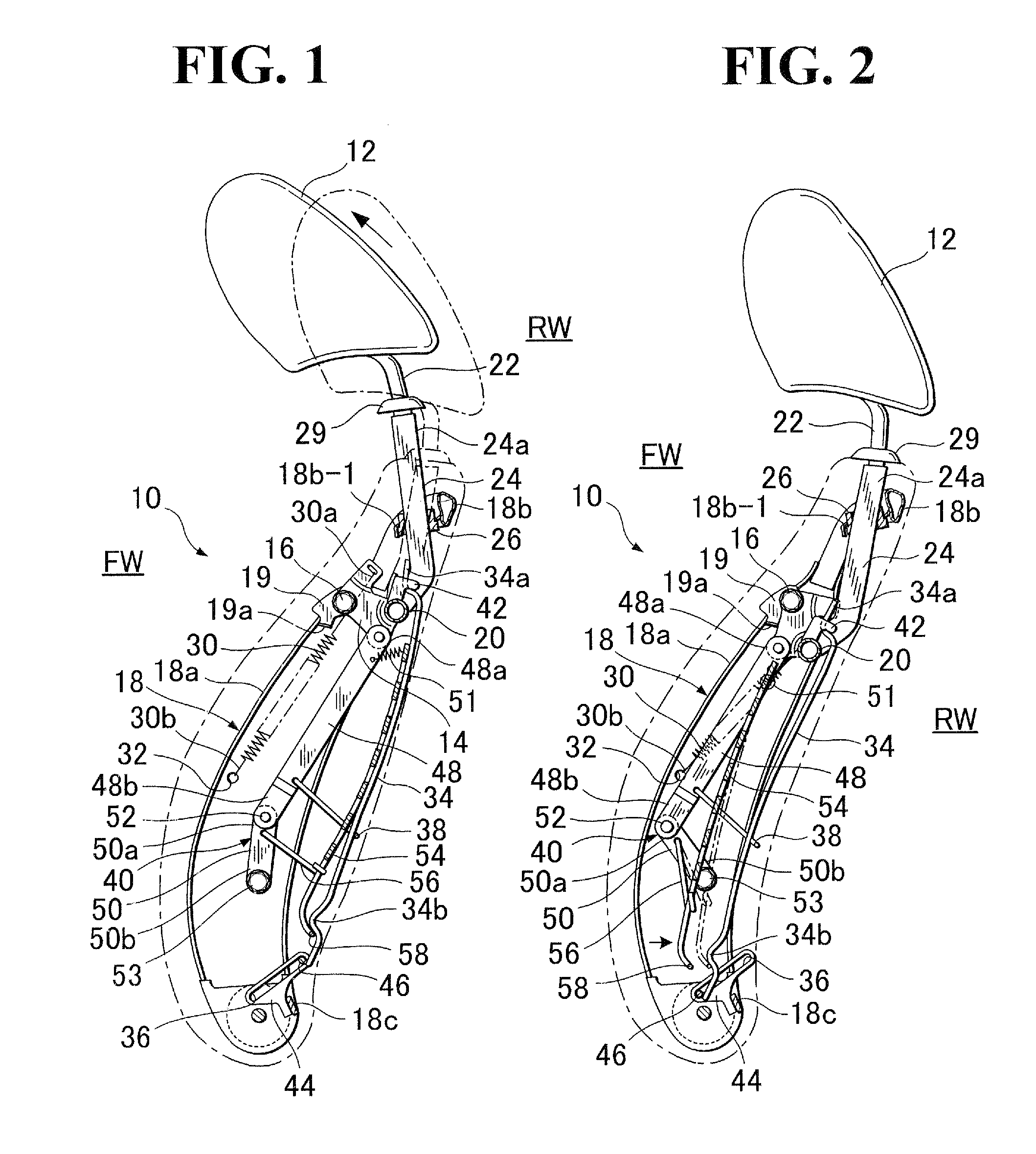
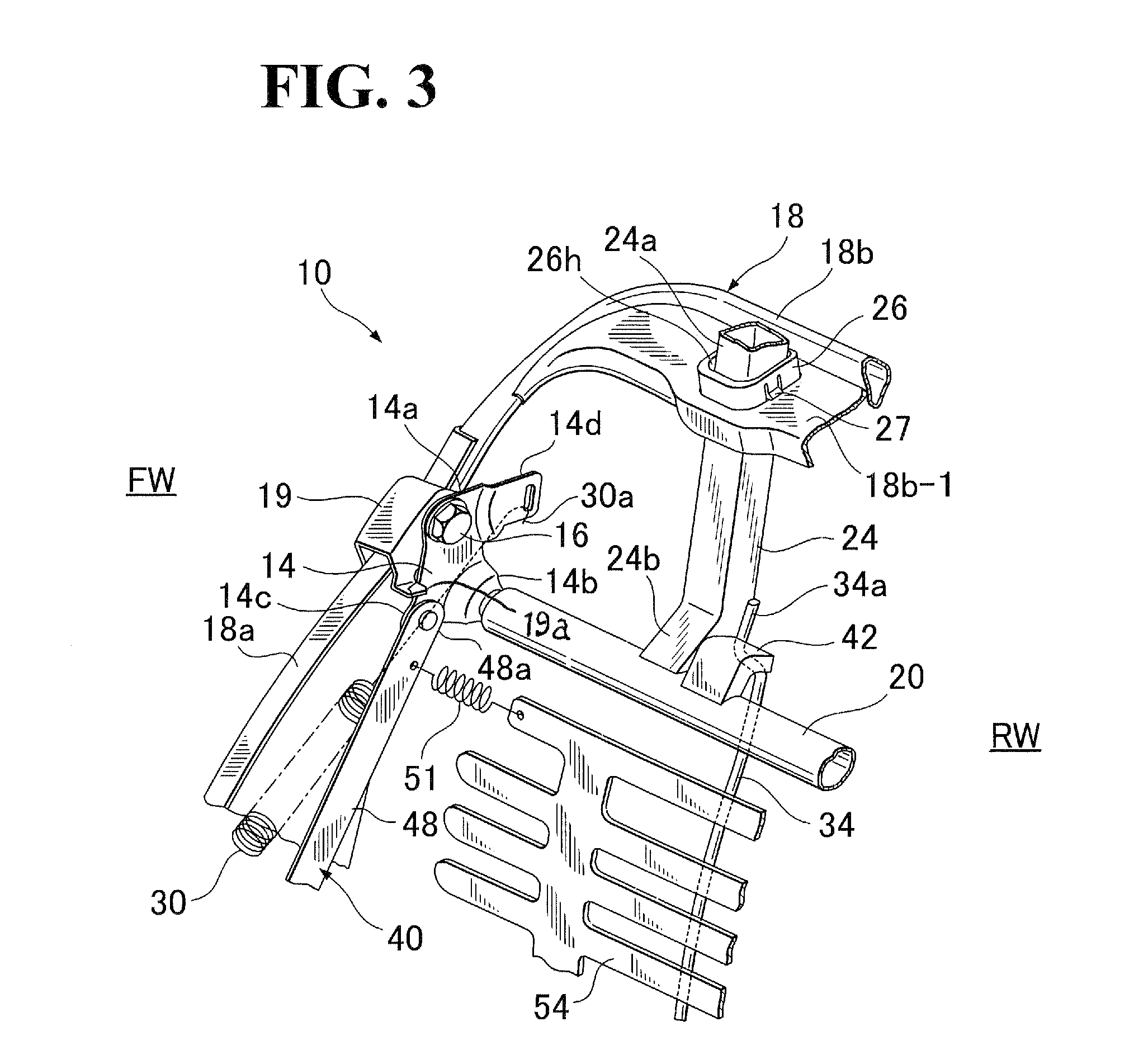
[0031]Referring to FIGS. 1 to 6, there is illustrated a preferred exemplary embodiment of seat back structure of vehicle seat in accordance with the preset invention. It is noted that the vehicle seat itself is not shown in the drawings, which comprises a seat back (10) to be elaborated hereinafter and an unshown seat cushion, but, it should be understood that a seat occupant (not shown) is to sit on the vehicle seat and rest his or her lumbar and dorsal parts on the seat back (10).

[0032]FIG. 1 is a schematic longitudinal sectional view for structurally depicting the inside of the seat back (10). As shown, in accordance with the present invention, the seat back (10) is provided with an headrest (12) of an emergency active type workable in rear-end collision case, wherein, when a rear-end collision occurs, in response to a backward great pressure applied from a seat occupant on the vehicle seat under a backward inertia of the seat occupant, the headrest (12) will be immediately displ...


PUM


Abstract

A seat back structure with headrest includes a vertical pressure-receiving element and cross pressure-receiving element. The headrest is fixed on a support rod operatively connected via a rotating link with an actuator link assembly. The vertical pressure-receiving element, upon one load being applied thereto from a seat occupant's lumber part, is displaced backwardly and upwardly via guide hole to push the support rod, thereby causing commencement of rotation of the rotating links to move the headrest upwardly. Thereafter, the cross pressure-receiving element, connected with the actuator link assembly, is displaced backwardly, upon another load being applied thereto from a seat occupant's dorsal part, thereby assisting in continuation of the rotation of rotating link.

Description


Claims


Application Information

Patent Timeline
Owner TACHI S CO LTD
Why Eureka
Try Eureka