3-D Displays and Telepresence Systems and Methods Therefore

a display and telepresence technology, applied in the field of video conferencing equipment, can solve the problems of excessive bulky display system, achieve the effect of avoiding adverse image brightness, effective delivery of video images, and optimizing the quality of delivery

Active Publication Date: 2008-01-17
TELEPRESENCE TECH
View PDF61 Cites 67 Cited by
  • Summary
  • Abstract
  • Description
  • Claims
  • Application Information

AI Technical Summary

Benefits of technology

[0026] Another advantage of the present invention is that the backdrop can be a backlit transparency. Since this backdrop image is preferably illuminated from behind, the brightness of the image will not be adversely affected by the ambient lighting in the room. The backlit illuminated transparency can be a graphic image, photographic image, montage or patterned surface that is optimal for brightness and composition to achieve the desired visual effect for the backdrop.
[0027] An embodiment of the invention could include the network connection, which could be over an ISDN network or an IP network. The output of the computer from the send location could be directed through the codec to transmit a computer image at the second image display device at the remote location.
[0028] Another aspect of the invention is the communication between two locations using telepresence communications systems. In this aspect, the system architecture incorporates a network connection between computers in each of the telepresence communication locations to establish interaction with data sharing applications. For optimizing the quality of the delivery of both the supporting computer generated visuals and the effective delivery of the video images of the telepresence systems, it is preferable to use an IP network that is optimized for telepresence. This telepresence network would need to meet specific requirements of a minimal latency and quality of service, which are currently not possible when transmitting on the public Internet and most virtual private networks.
[0029] In yet another aspect, the present invention pr

Problems solved by technology

However, the requirement for a physical backdrop behind th

Method used


Image

  • 3-D Displays and Telepresence Systems and Methods Therefore
  • 3-D Displays and Telepresence Systems and Methods Therefore
  • 3-D Displays and Telepresence Systems and Methods Therefore

Examples


Embodiment Construction

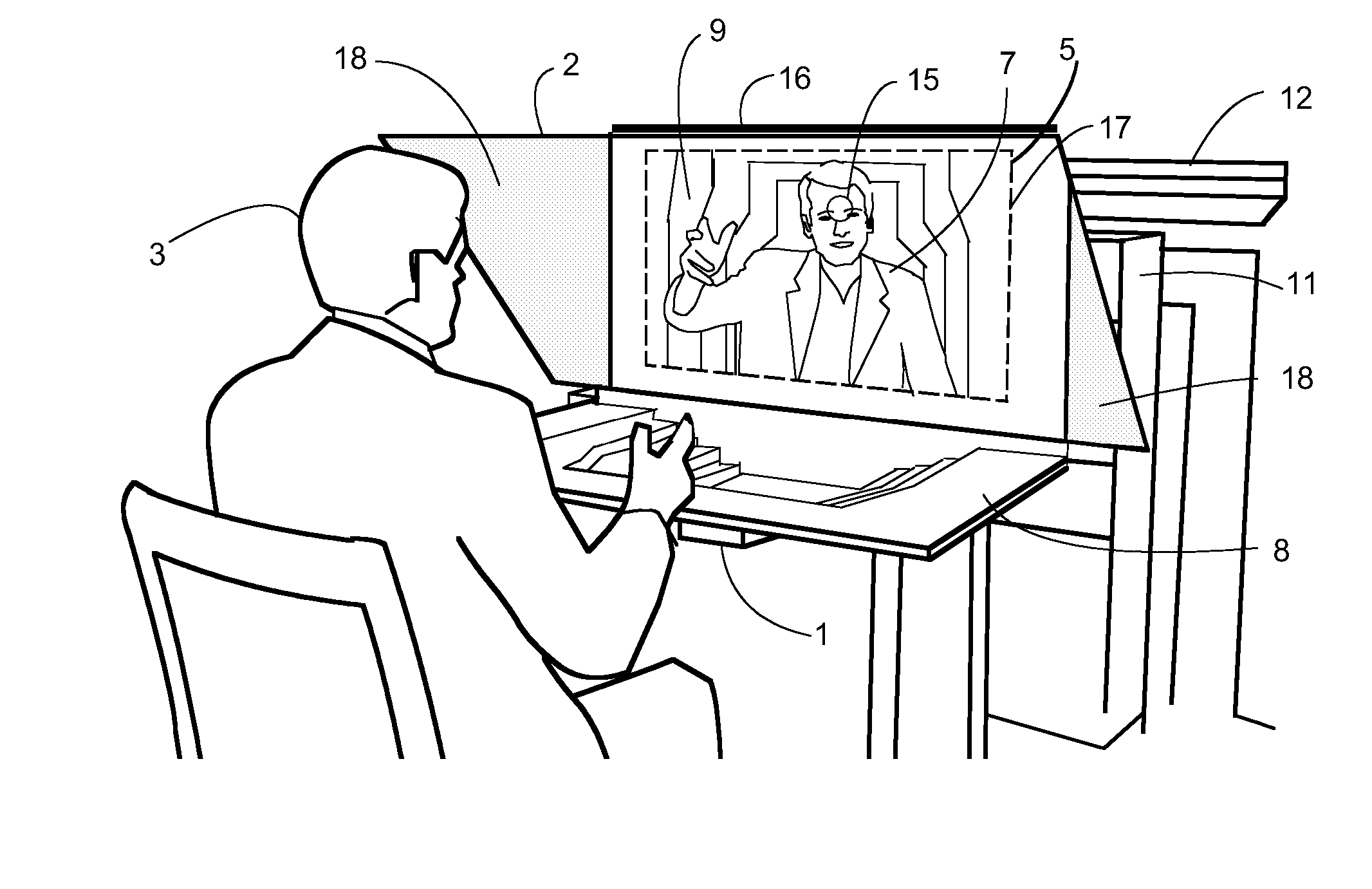
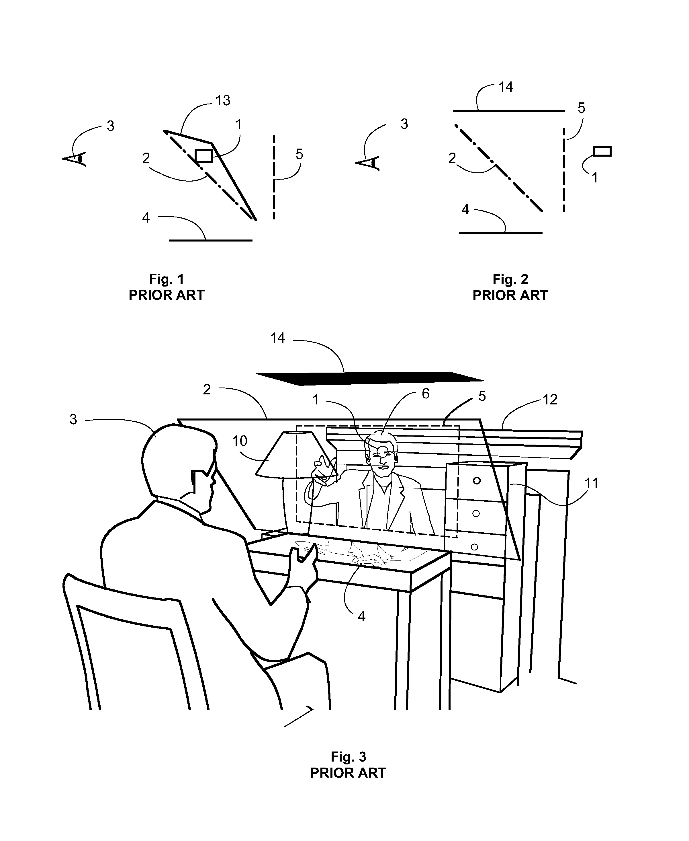
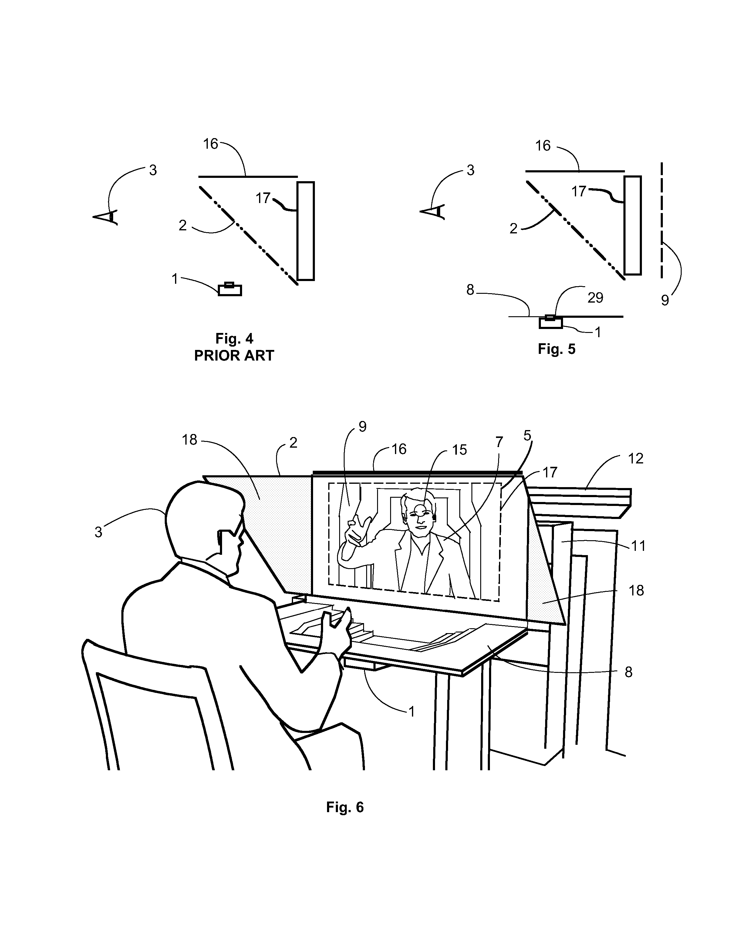
[0150] Embodiments and advantages of the invention will be discussed in general terms, first, followed by a more detailed description of specific preferred embodiments. The telepresence communications system is comprised of an image on an image display device, which is positioned directly behind the two-way mirror. The image display device may be a flat panel plasma or LCD monitor, rear projection video system, front projection on a screen or other image display method capable of displaying moving images. For the purpose of clarity, the vertical plane of the image on the image display system is described as a first plane. A second plane is described as a plane parallel to the first plane and further away from the user. A backdrop is positioned further away from the two-way mirror than the image on the image display device so that a reflection of the backdrop appears in the location of the second plane. The two-way mirror and the backdrop are set at angles that will result in the ref...


PUM


Abstract

A telepresence system enhances the perception of presence of a remote person involved in a video conference. The system preferably has a two-way mirror, which is between the observer and the display device, positioned at an angle to reflect a backdrop surface. The backdrop surface, which is further away from the two-way mirror than the image plane of the image display device, appears superimposed in a position behind the image of a person from the remote location. The system preferably minimizes image distortion via an optical path for the camera line of sight that is substantially longer than the physical distance between the user and the camera. The system may be asymmetrical, in that one camera is on axis with the user's line of sight while the other camera is off axis with the user's line of sight.

Description

[0001] This application is a continuation-in-part of non-provisional U.S. patent application Ser. No. 11 / 085,292, filed Mar. 21, 2005, incorporated herein by reference, which is a continuation-in-part of non-provisional U.S. patent application Ser. No. 10 / 897,453, filed Jul. 23, 2004 (U.S. Pat. No. 7,057,637), incorporated herein by reference, which claims priority to provisional U.S. Patent Application Ser. No. 60 / 564,098, filed Apr. 21, 2004, also incorporated herein by reference. [0002] This application also claims priority to provisional U.S. Patent Application Ser. No. 60 / 846,415, filed Sep. 22, 2006, incorporated herein by reference, and to provisional U.S. Patent Application Ser. No. 60 / 855,065, filed Oct. 27, 2006, incorporated herein by reference, and to provisional U.S. Patent Application Ser. No. 60 / 968,447, filed Aug. 28, 2007, incorporated herein by reference.TECHNICAL FIELD [0003] The present invention relates to video conferencing apparatus and more particularly to sy...

Claims


Application Information

Patent Timeline
IPC IPC(8): H04N7/14H04N13/04
CPCH04N7/15H04N7/144
Inventor WHITE, PETER MCDUFFIE
Owner TELEPRESENCE TECH
Why Eureka
Try Eureka