Stylus with integrated RFID chip

a technology of rfid chip and rfid chip, which is applied in the direction of measuring/indication equipment, electrical/magnetic measuring arrangement, testing/calibration of speed/acceleration/shock measurement device, etc., can solve the problem of time- and cost-intensive procedures

Inactive Publication Date: 2008-01-24
SAPHIRWERK INDPROD
View PDF12 Cites 94 Cited by
  • Summary
  • Abstract
  • Description
  • Claims
  • Application Information

AI Technical Summary

Benefits of technology

[0006]It is an object of the present invention to make available a measurement device and method which make it possible to automate measurement procedures and make them more profitable.

Problems solved by technology

Such a procedure is time- and cost-intensive when a large number of measurements are involved.

Method used


Image

  • Stylus with integrated RFID chip
  • Stylus with integrated RFID chip

Examples


Embodiment Construction

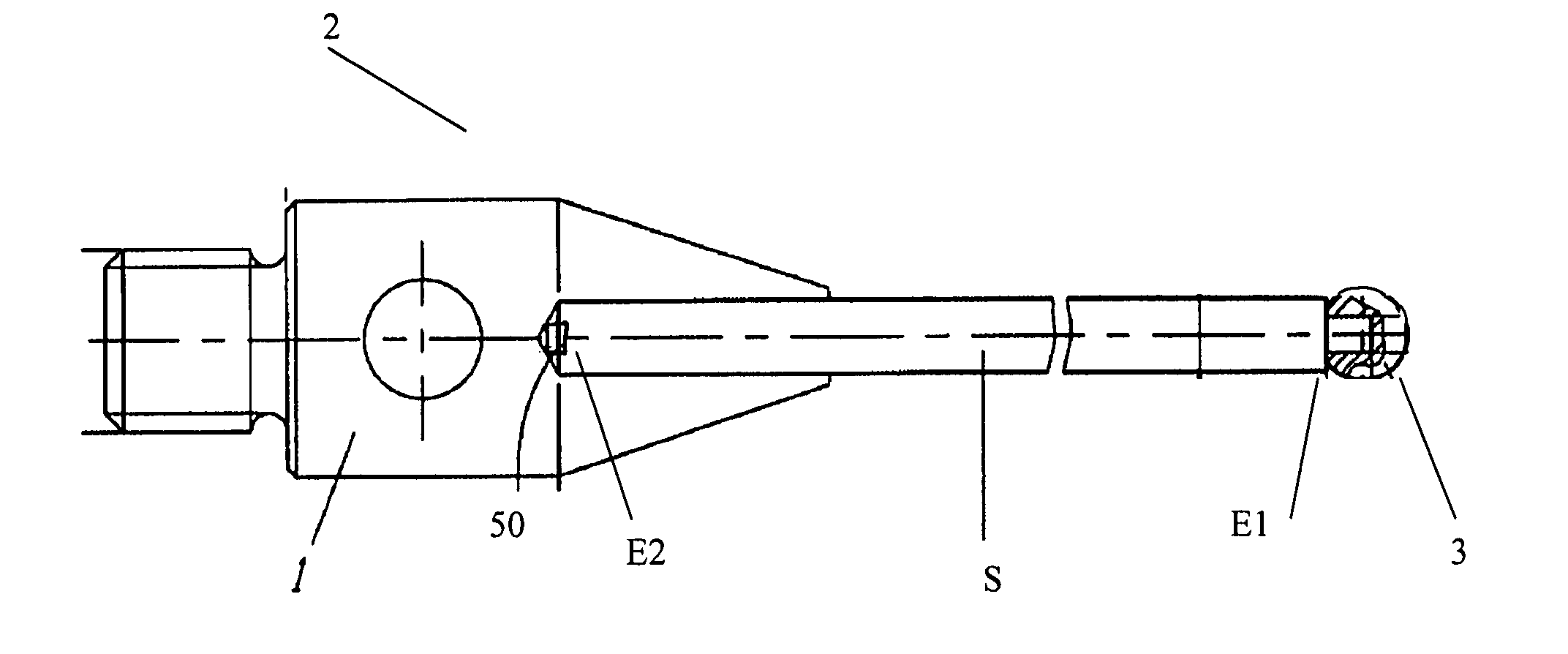
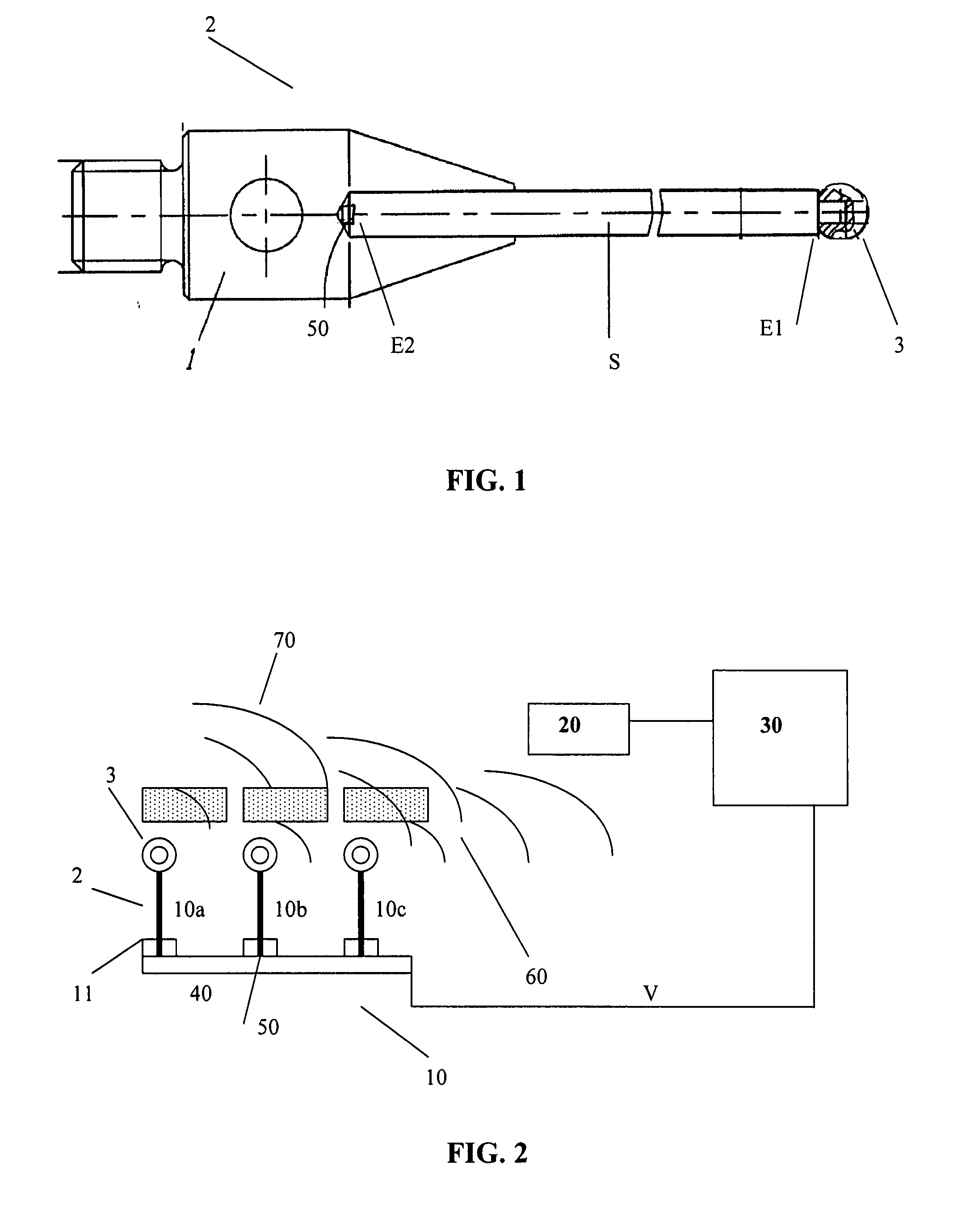
[0039]In FIG. 1a top view of the stylus 2 according to the invention with an integrated RFID chip is shown.

[0040]The stylus 2 has a stem S with a first end E1 and a second end E2. The geometry of the stem (S) of the stylus 2 corresponds to a cylinder, wherein its first end E1 has a tapered cylindrical end, onto which is glued as contact element a sphere 3 which is brought into contact with the measured object during a measurement procedure.

[0041]The second end E2 of the stylus 2 has a frustum-shaped form which at its end into which the RFID chip 50 according to the invention is glued has a recess in the form of a bore.

[0042]The stylus 2 is introduced with its second end E2 into a holder 1, which has a cylindrical recess. The connection between the stem S of the stylus and the holding device 1 can be carried out by adhesive, a soldering process, a shrink fit or a press fit etc. or their combinations. The connection between the stylus 2 and the holding device or the sensor head 1 is a...


PUM


Abstract

A stylus includes a stem with a first end and a second end, wherein the stem includes a contact element at the first end and can be arranged with the second end in a holder, and wherein the stylus includes an RFID chip. Also, a measurement device including the stylus and a method for taking account of data characterizing the stylus in a measurement device is provided.

Description

[0001]This claims the benefit of German Patent Application No. 10 2006 033 443.4, filed on Jul. 19, 2006, and hereby incorporated by reference herein.[0002]The present invention relates generally to a stylus.BACKGROUND[0003]Manufacturing and measurement procedures are increasingly automated today on economic grounds.[0004]Special measurement procedures which use special styli need the bending characteristics or distortion of these styli, obtainable from manufacturer-specific characteristic data or error data. Such error data are today mostly integrated manually when evaluating measurement procedures. Such a procedure is time- and cost-intensive when a large number of measurements are involved.[0005]A method for measuring the bending characteristics or distortion data of styli by means of a calibrating device has already been described in detail in EP 1248073 B1.SUMMARY OF THE INVENTION[0006]It is an object of the present invention to make available a measurement device and method wh...

Claims


Application Information

Patent Timeline
Patent Type & Authority Applications(United States)
IPC IPC(8): G01B7/00
CPCG01B21/047G01B7/012
Inventor BAEBLER, JEAN
Owner SAPHIRWERK INDPROD
Why Eureka
Try Eureka