Rotation transmission member and manufacturing method therefor

Inactive Publication Date: 2008-01-24
ADVICS CO LTD
View PDF8 Cites 19 Cited by
  • Summary
  • Abstract
  • Description
  • Claims
  • Application Information

AI Technical Summary

Benefits of technology

[0010]Accordingly, it is a primary object of the present invention to provide an improved rotation transmission member and a manufacturing method therefor in which the machining of

Problems solved by technology

Because the technology described in the aforementioned prior art is of the method that a part of resin material is filled in the cutouts or holes formed on the metal part (metal member) at the time of the injection molding of the resin gear section,

Method used


Image

  • Rotation transmission member and manufacturing method therefor
  • Rotation transmission member and manufacturing method therefor
  • Rotation transmission member and manufacturing method therefor

Examples


first embodiment

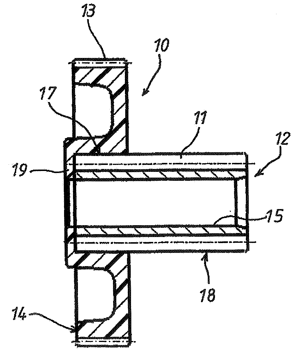
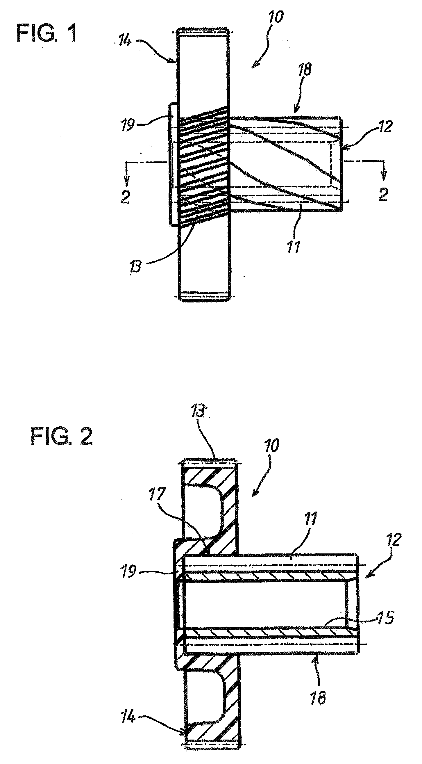
[0023]Hereafter, a rotation transmission member in a first embodiment according to the present invention will be described with reference to FIGS. 1 and 2. The rotation transmission member 10 is composed of a shaft-like metal insert member 12 having a first gear section 11 formed as helical gear and a resin gear 14 having a second gear section 13 formed as helical gear. The resin gear 14 is resin-molded by insert molding on the external surface of one end of the metal insert member 12 and is formed bodily with the same.

[0024]The metal insert member 12 has a through hole 15 on its center axis and has the first gear 11 formed helically on the external surface over the entire length thereof. The metal insert member 12 defines an insert portion 17 on which the resin gear 14 is resin-molded by insert molding, at one axial end thereof and also defines a gear transmission portion 18 at the other axial end thereof.

[0025]The resin gear 14 takes the shape of a disc, which has an axial length ...

second embodiment

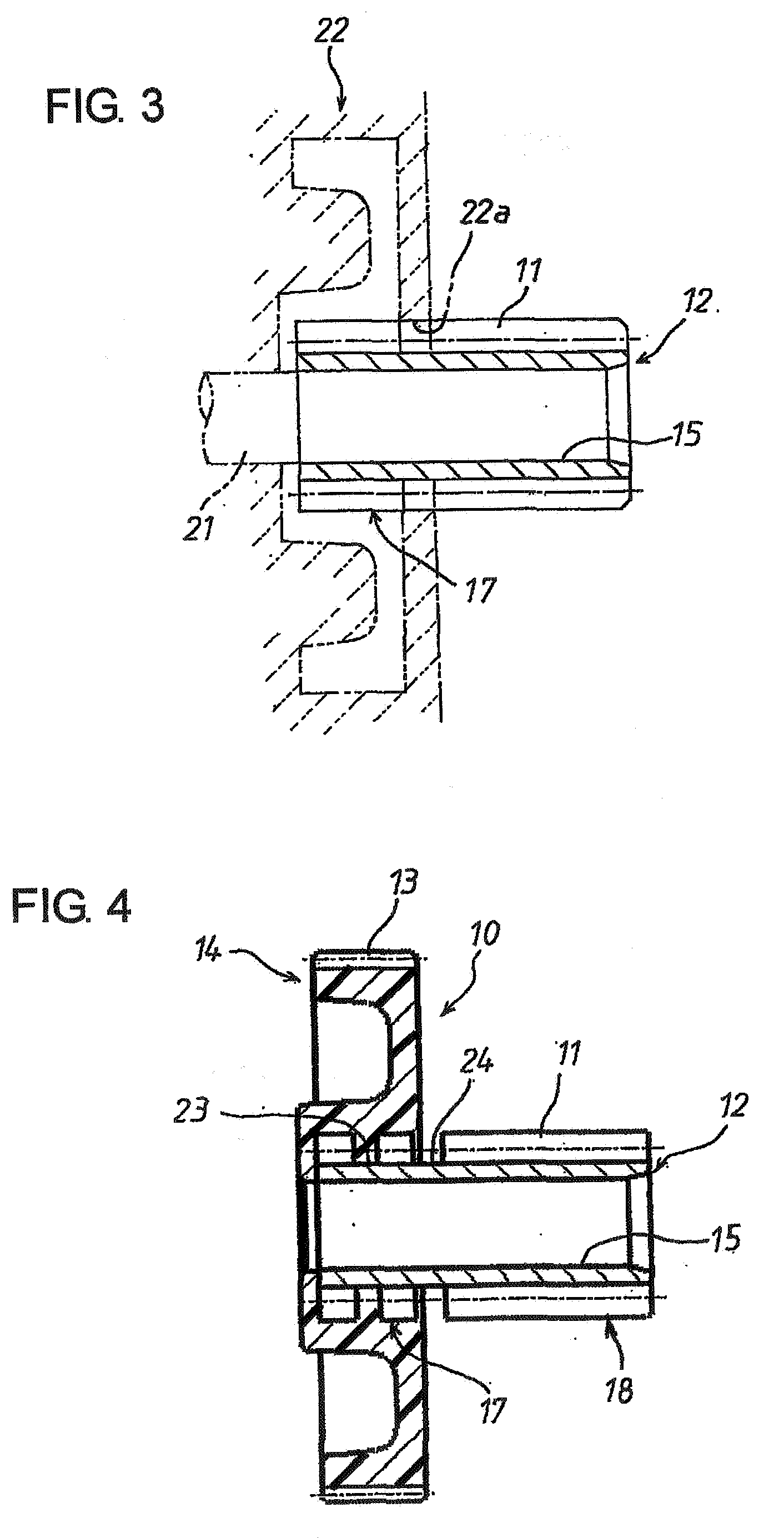
[0030]FIG. 4 shows a rotation transmission member in a second embodiment according to the present invention. The same components in the second embodiment as those in the foregoing first embodiment are designated by the same reference numerals, and description of such same components will be omitted for the sake of brevity. The rotation transmission member 10 in the second embodiment is increased in its strength against the coming-off of the resin gear 14 relative to the metal insert member 12. More specifically, in the second embodiment, after the first gear section 11 is helically machined on the external surface of the metal insert member 12 over the entire axial length thereof, the insert member 12 is machined to have a first annular groove 23 at about the middle in the axial direction of the insert portion 17. The insert member 12 is further machined to have a second annular groove 24 between the insert portion 17 and the transmission gear portion 18. When the resin-molding is p...

third embodiment

[0032]FIGS. 5 and 6 show a rotation transmission member in a third embodiment according to the present invention. In the third embodiment, spur gears are formed as the first and second gear sections 111, 113 which are provided on the metal insert member 12 and the resin gear 14, respectively. The first gear section 111 is provided with an annular groove 123 similar to that in the foregoing second embodiment, at the axial mid position of the insert portion 17. By means of the annular groove 123, it can be ensured to prevent the resin gear 14 from coming off the metal insert member 12.

[0033]Where the first and second gear sections 11, 113 are formed as super gears, the rotation hardly applies any substantial load in the thrust direction on the metal insert portion 12 and the resin gear 14. Thus, only by resin-molding the resin gear 14 on the insert portion 17 of the gear section 111 formed as super gear without particularly providing any annular groove on the first gear section 111, i...


PUM

PropertyMeasurementUnit
Lengthaaaaaaaaaa

Abstract

A rotation transmission member is composed of a shaft-like metal insert member having a first gear section on the external surface thereof and a resin gear resin-molded on the external surface of one end of the metal insert member and having a second gear section on the external surface thereof. The first gear section is formed almost over the entire length of the metal insert member and provides one end thereof as an insert portion on which the resin gear is to be resin-molded. Thus, it becomes unnecessary to provide a joint portion (the insert portion) between the metal insert member and the resin gear with the machining of any particular shape for preventing the coming-off therebetween.

Description

INCORPORATION BY REFERENCE[0001]This application is based on and claims priority under 35 U.S.C. 119 with respect to Japanese Application No. 2006-196353 filed on Jul. 19, 2006, the entire content of which is incorporated herein by reference.BACKGROUND OF THE INVENTION[0002]1. Field of the Invention[0003]The present invention relates to a rotation transmission member in which a resin gear is molded by insert molding on the external surface of one end of a gear section formed almost over the entire length of a metal insert member. It also relates to a method of manufacturing the rotation transmission member.[0004]2, Discussion of the Related Art[0005]Automotive parts often use resin gear sections for rotation transmission at parts of a rotation transmission device. Such resin gear sections are useful because they can damp rotation vibration in a rotation transmission train to enhance quietness. Generally, a resin gear section is bodily joined by resin molding or the like with the ext...

Claims


Application Information

Patent Timeline
IPC IPC(8): F16H55/17B21D53/28
CPCF16H55/06F16H55/17F16H2055/065Y10T74/19907Y10T29/49467Y10T74/19912Y10T74/19888
Inventor WATANABE, KENJI
Owner ADVICS CO LTD
Why Eureka
Try Eureka