Self-charging RFID tag with long life

a self-charging, battery-powered technology, applied in the direction of burglar alarm mechanical actuation, burglar alarm by hand-held articles removal, instruments, etc., can solve the problems of billion dollar inventory visibility problem, limited speed and reliability of line-of-sight process, and often damaged or lost outer labels, so as to save battery power

Active Publication Date: 2008-01-24
ZEST LABS INC
View PDF54 Cites 51 Cited by
  • Summary
  • Abstract
  • Description
  • Claims
  • Application Information

AI Technical Summary

Benefits of technology

[0017]A Radio Frequency Identification (RFID) tag for use with a vehicle according to one embodiment includes a housing adapted for permanent or detachable coupling to the vehicle, control circuitry coupled to the housing, and a solid state battery for providing power to the control circuitry. A supplemental power source is also present for recharging the battery. A memory stores information relating to at least one of the vehicle and an owner of the vehicle. The capability of recharging the battery greatly extends the active (self-powered) life of the tag.
[0020]Preferably, the control circuitry draws power from the supplemental power source when the supplemental power source is generating electricity. This also helps conserve battery power, as well as allows the tag to operate when the battery is diminished. The control circuitry may remain in an active state when drawing power from the supplemental power source, as opposed to reverting to a battery-conserving hibernate state.

Problems solved by technology

However, the bar code still requires manual interrogation by a human operator to scan each tagged object individually with a scanner.
This is a line-of-sight process that has inherent limitations in speed and reliability.
In transit, these outer labels are often damaged or lost.
Error rates at each point in the supply chain have been 4-18% thus creating a billion dollar inventory visibility problem.
One drawback of such systems is that the battery does not have an infinite life.
However, not only does the automobile need to be retrofitted to provide the power line to the tag, but the tag is then permanently mounted to the vehicle, meaning that if the owner decides to drive another car on the toll road or bridge, the driver must wait in line to pay at a toll booth rather than pass through the automated toll lane.
However, as mentioned above, the life of the battery is not infinite, and so the tag will likely not remain active for the entire life of the object to which coupled.
The tag may still respond to queries in a passive mode if it has built in multi-protocols and has C1G2 capability, where the tag is powered by the incoming RF signal, but the range for such communication is severely limited and may not be suitable for applications involving fast moving items such as automobiles, or in situations where an RFID interrogator is not readily available within range of the tag.
However, such rechargeable batteries typically provide less power per charge than a comparable disposable battery, and so need to be recharged rather frequently.
Unfortunately, such rechargeable batteries do not have a large number of charge / recharge cycles.
Rather, such rechargeable batteries lose capacity each time they are recharged, and therefore may only be recharged a handful of times before completely losing the ability to carry a charge sufficient for tag operations.

Method used


Image

  • Self-charging RFID tag with long life
  • Self-charging RFID tag with long life
  • Self-charging RFID tag with long life

Examples


Embodiment Construction

[0041]The following description is the best mode presently contemplated for carrying out the present invention. This description is made for the purpose of illustrating the general principles of the present invention and is not meant to limit the inventive concepts claimed herein. Further, particular features described herein can be used in combination with other described features in each of the various possible combinations and permutations.

[0042]Unless otherwise specifically defined herein, all terms are to be given their broadest possible interpretation including meanings implied from the specification as well as meanings understood by those skilled in the art and as defined in dictionaries, treatises, etc.

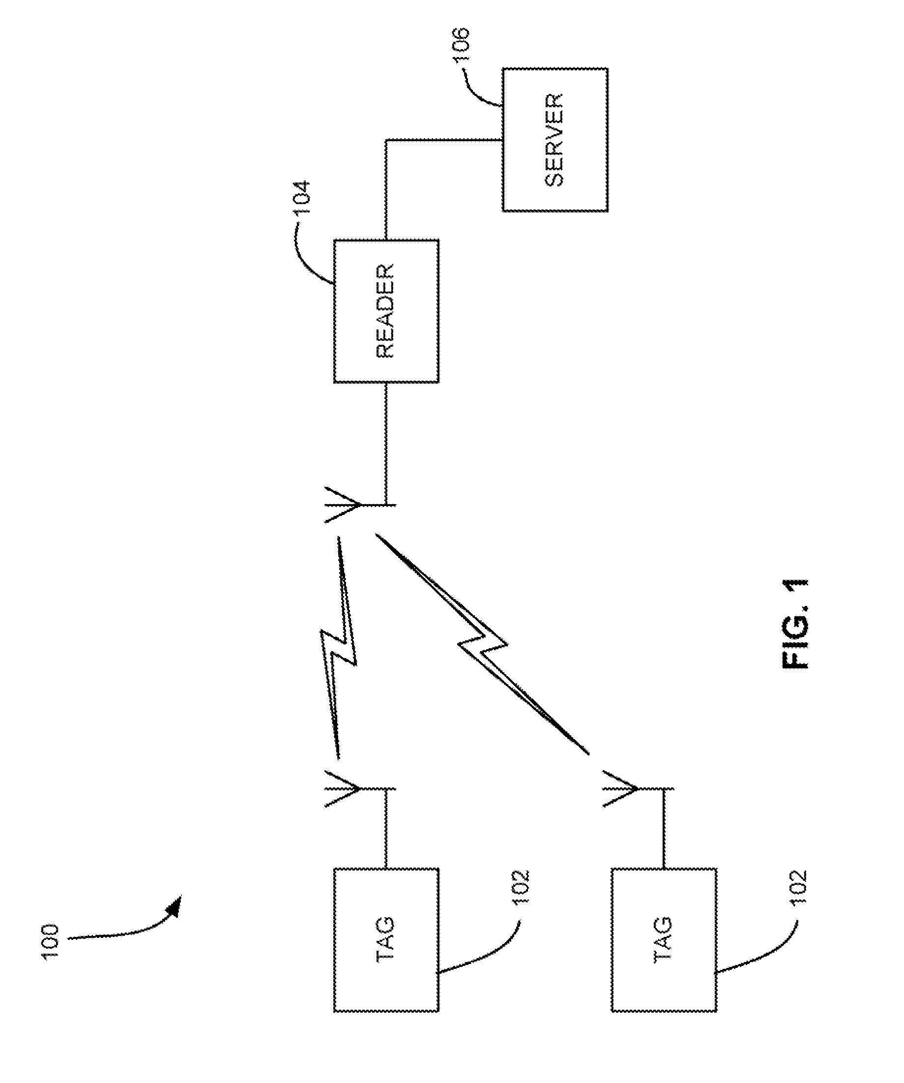
[0043]The use of RFID tags are quickly gaining popularity for use in the monitoring and tracking of an item. RFID technology allows a user to remotely store and retrieve data in connection with an item utilizing a small, unobtrusive tag. As an RFID tag operates in the radio fr...


PUM


Abstract

A Radio Frequency Identification (RFID) device according to one embodiment of the present invention includes a rechargeable solid state battery, control circuitry coupled to the rechargeable solid state battery, and a power source for recharging the rechargeable solid state battery.

Description

FIELD OF THE INVENTION[0001]The present invention relates to Radio Frequency Identification (RFID) systems and methods, and more particularly, this invention relates to RFID tags with a rechargeable battery.BACKGROUND OF THE INVENTION[0002]Automatic identification (“Auto-ID”) technology is used to help machines identify objects and capture data automatically. One of the earliest Auto-ID technologies was the bar code, which uses an alternating series of thin and wide bands that can be digitally interpreted by an optical scanner. This technology gained widespread adoption and near-universal acceptance with the designation of the Universal Product Code (“UPC”)—a standard governed by an industry-wide consortium called the Uniform Code Council. Formally adopted in 1973, the UPC is one of the most ubiquitous symbols present on virtually all manufactured goods today and has allowed for enormous efficiency in the tracking of goods through the manufacturing, supply, and distribution of vario...

Claims


Application Information

Patent Timeline
Patent Type & Authority Applications(United States)
IPC IPC(8): G08B13/14
CPCG06K19/0702G06K19/07749G06K19/0707
Inventor BATRA, NARESHOLAH, ROBERT
Owner ZEST LABS INC
Why Eureka
Try Eureka