RFID systems and methods

Active Publication Date: 2007-12-13
KOTAB DOMINIC
View PDF70 Cites 81 Cited by
  • Summary
  • Abstract
  • Description
  • Claims
  • Application Information

AI Technical Summary

Benefits of technology

[0010]A Radio Frequency Identification (RFID) tag for use with a vehicle according to one embodiment includes a housing adapted for permanent or detachable coupling to the vehicle, control circuitry coupled to the housing, and a battery for providing power to the control ci

Problems solved by technology

However, the bar code still requires manual interrogation by a human operator to scan each tagged object individually with a scanner.
This is a line-of-sight process that has inherent limitations in speed and reliability.
In transit, these outer labels are often damaged or lost.
Error rates at each point in the supply chain have been 4-18% thus creating a billion dollar inventory visibility problem.
One drawback of such systems is that the battery does not have an infinite life.
However, not only does the automobile need to be retrofitted to provide the power line to the tag, but the tag is then permanently mounted to the vehicle, meaning that if the owner decide

Method used


Image

  • RFID systems and methods
  • RFID systems and methods
  • RFID systems and methods

Examples


Example

[0036]The following description is the best mode presently contemplated for carrying out the present invention. This description is made for the purpose of illustrating the general principles of the present invention and is not meant to limit the inventive concepts claimed herein. Further, particular features described herein can be used in combination with other described features in each of the various possible combinations and permutations.

[0037]Unless otherwise specifically defined herein, all terms are to be given their broadest possible interpretation including meanings implied from the specification as well as meanings understood by those skilled in the art and as defined in dictionaries, treatises, etc.

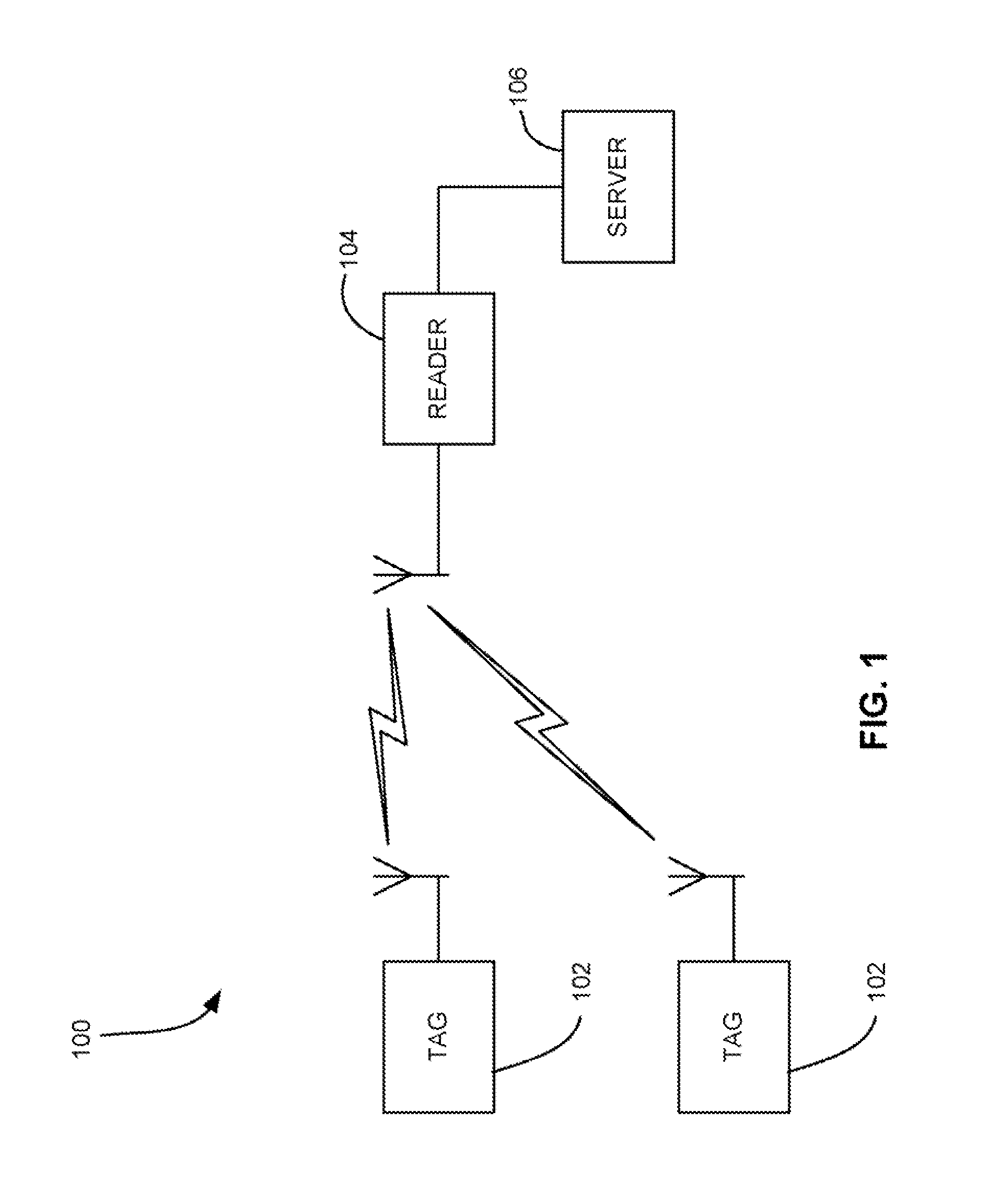
[0038]The use of RFID tags are quickly gaining popularity for use in the monitoring and tracking of an item. RFID technology allows a user to remotely store and retrieve data in connection with an item utilizing a small, unobtrusive tag. As an RFID tag operates in the radio fr...


PUM


Abstract

A Radio Frequency Identification (RFID) tag for use with a vehicle according to one embodiment includes a housing adapted for permanent or detachable coupling to the vehicle, control circuitry coupled to the housing, and a battery for providing power to the control circuitry. A secondary power source is also present for recharging the battery. A memory stores information relating to at least one of the vehicle and an owner of the vehicle. The capability of recharging the battery greatly extends the active (self-powered) life of the tag. Systems for tracking ownership of objects, servicing of vehicles, and other applications, as well as methods are also presented.

Description

FIELD OF THE INVENTION[0001]The present invention relates to Radio Frequency Identification (RFID) systems and methods, and more particularly, this invention relates to systems and methods for tracking and singulating tagged objects.BACKGROUND OF THE INVENTION[0002]Automatic identification (“Auto-ID”) technology is used to help machines identify objects and capture data automatically. One of the earliest Auto-ID technologies was the bar code, which uses an alternating series of thin and wide bands that can be digitally interpreted by an optical scanner. This technology gained widespread adoption and near-universal acceptance with the designation of the Universal Product Code (“UPC”)—a standard governed by an industry-wide consortium called the Uniform Code Council. Formally adopted in 1973, the UPC is one of the most ubiquitous symbols present on virtually all manufactured goods today and has allowed for enormous efficiency in the tracking of goods through the manufacturing, supply,...

Claims


Application Information

Patent Timeline
IPC IPC(8): G08B13/14G06K19/06
CPCG08B13/2462G01M5/00G06K19/0704G06K19/07707G06K19/07758
Inventor BATRA, NARESH
Owner KOTAB DOMINIC
Why Eureka
Try Eureka