Electron gun and electron beam device

Inactive Publication Date: 2014-02-27
PARAM
View PDF0 Cites 10 Cited by
  • Summary
  • Abstract
  • Description
  • Claims
  • Application Information

AI Technical Summary

Benefits of technology

[0025]According to the present invention, a holder covers the bottom and sides of an electron gun cathode, while the tip of the electron gun cathode protrudes from the holder. With thi

Problems solved by technology

The Vogel mount type electron gun cathode described above, which is formed of an LaB6 or CeB6 single crystal chip fixed by two pyrolytic graphite members on the respective sides with springs, has a disadvantage that the structure of the electron gun cathode is complicated, which makes alignment of the central axis of electrons relatively difficult.
Another disadvantage is that, because heating is performed by electric current, in the case of manufacturing a high voltage source for a multi-column device having, f

Method used


Image

  • Electron gun and electron beam device
  • Electron gun and electron beam device
  • Electron gun and electron beam device

Examples


Embodiment Construction

[0040]A preferred embodiment of the present invention will be described with reference to the drawings.

[0041]“Configuration of Electron Gun”

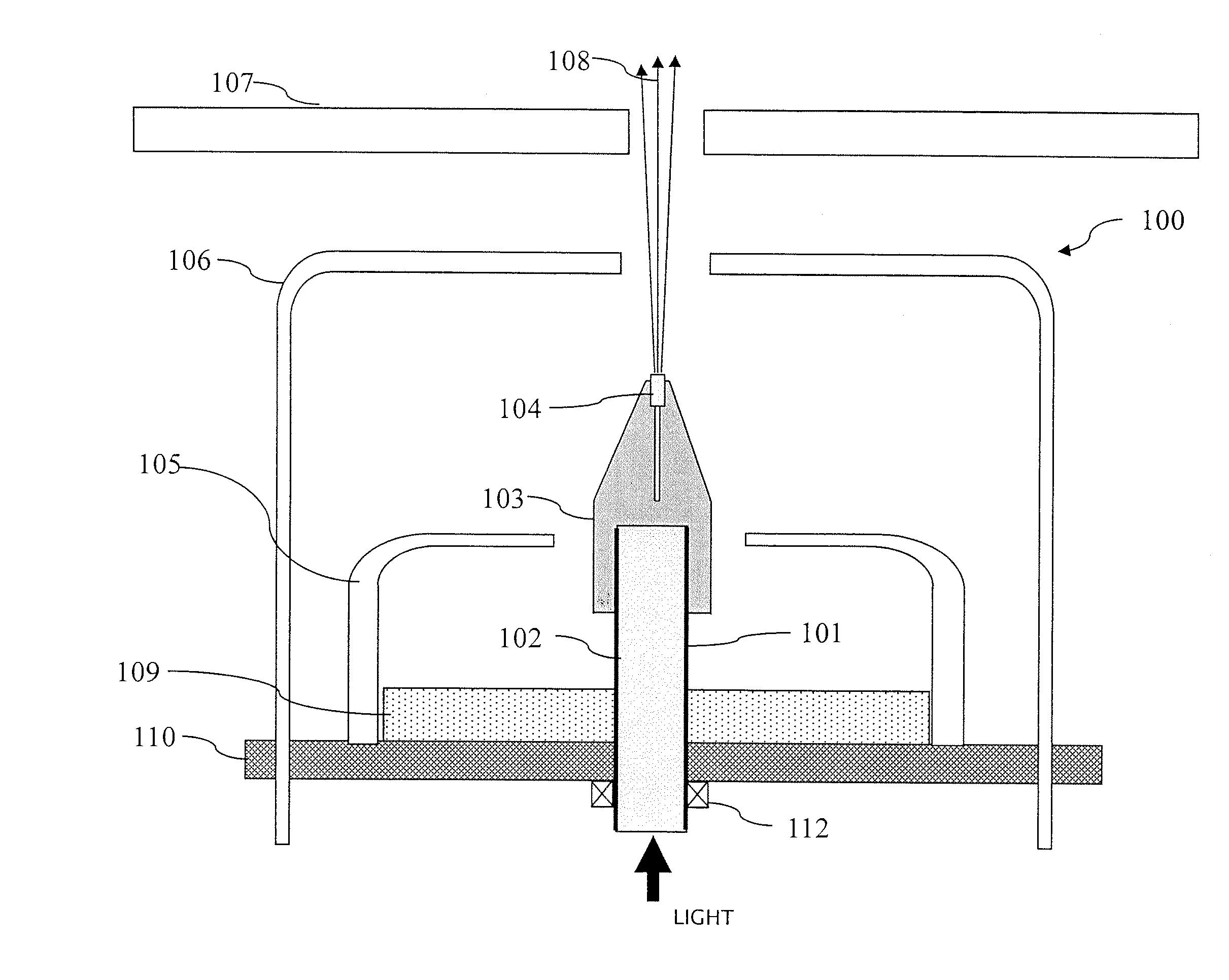
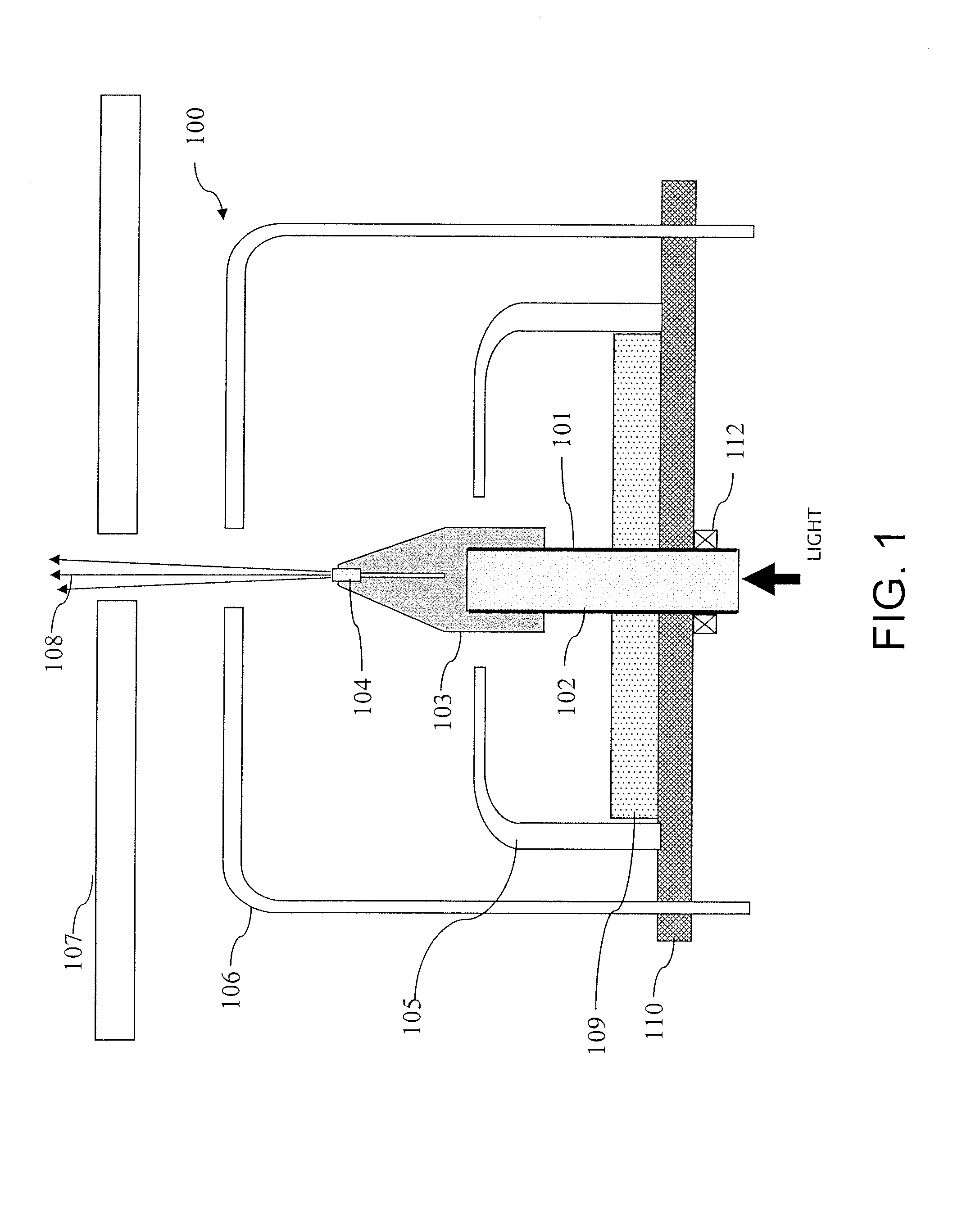
[0042]FIG. 1 is a view illustrating a configuration of an electron gun 100 according to an embodiment. In this example, the electron gun 100 adopts an optical heating method.

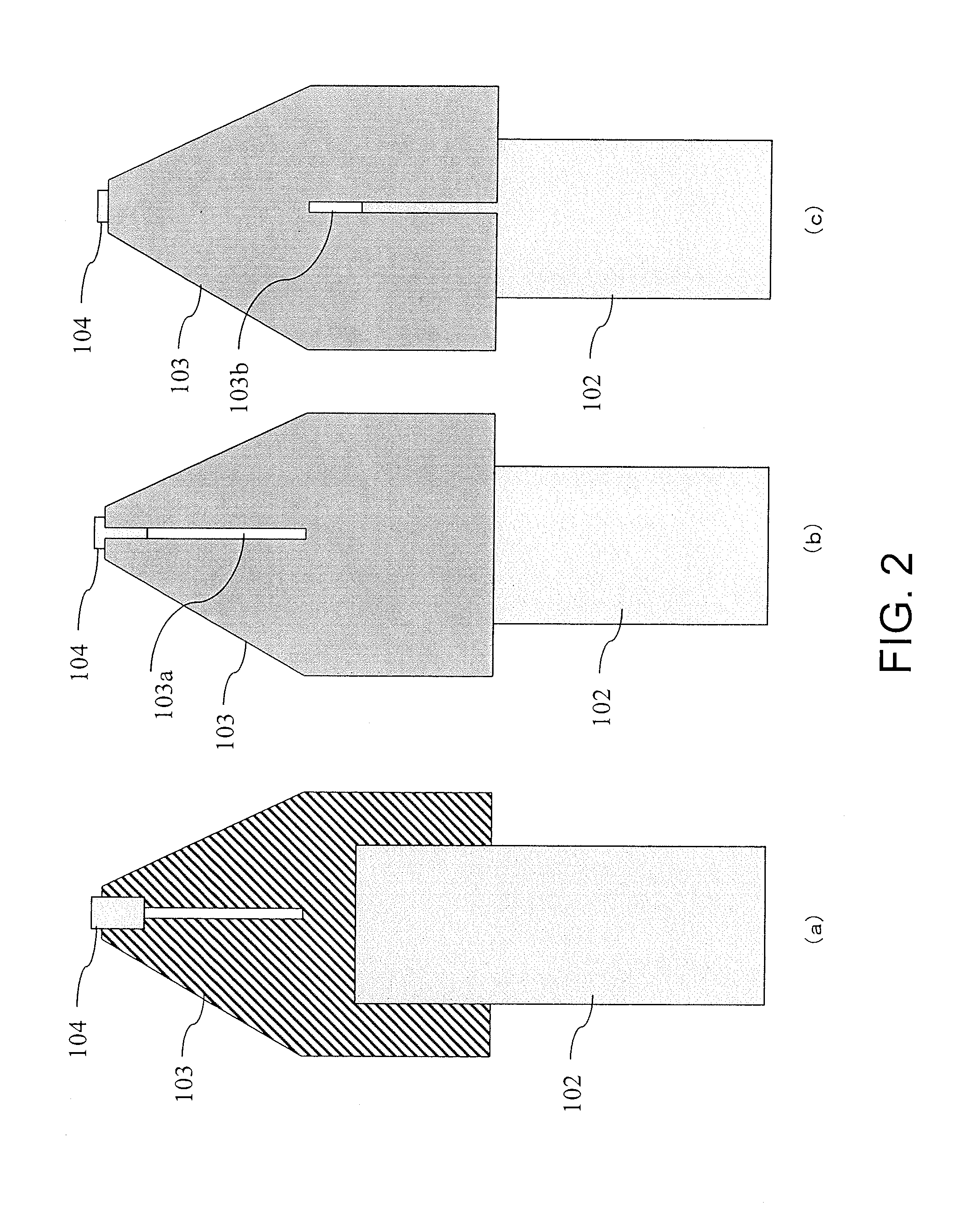
[0043]Referring to FIG. 1, light with a high energy density enters through one end portion (i.e., a light entry end at the lower portion in the figure) of a cylindrical optical waveguide 102 formed of sapphire, and further enters a holder 103 disposed on the opposite end portion (a tip portion) of the optical waveguide 102. In this example, the holder 103 is composed of a cylindrical portion on the base side and a conical portion on the tip side and is formed of rhenium as a whole. The holder 103 includes a cylindrical recess portion formed on the base side, into which the tip portion of the optical waveguide 102 is fitted.

[0044]The conical portion of the holder 103 has a tr...


PUM


Abstract

An electron gun cathode (104) is column shaped, and emits electrons by being heated. A holder (103), which covers the bottom and sides of the electron gun cathode, has electrical conductivity and holds the electron gun cathode, and is composed of a material that does not easily react with the electron gun cathode when in a heated state, is provided. The tip of the electron gun cathode (104) protrudes from the holder (103) so as to be exposed, and electrons are emitted from the tip toward the front by applying an electric field to the tip.

Description

TECHNICAL FIELD[0001]The present invention relates to an electron gun for emitting electrons. The present invention also relates to an electron beam device such as an electron beam exposure device or an electron beam inspection device such as an electron microscope, in which an electron gun is used.BACKGROUND ART[0002]In the field of lithography for exposing a circuit pattern in the process of manufacturing a semiconductor (LSI), electron beam exposure technology is being utilized. Specifically, in the semiconductor lithography technology, photochemical process technology (photolithography) has been mainly used, in which a mask, serving as an original pattern, is generally created by an electron beam exposure device and the mask image is optically transferred onto a semiconductor substrate (wafer).[0003]Electron beam exposure systems have been developed, starting from a method called one-stroke sketch (a picture drawn with a single stroke of the brush) with narrowly-focused electron...

Claims


Application Information

Patent Timeline
IPC IPC(8): H01J29/48
CPCH01J29/485H01J1/148H01J1/26H01J37/075H01J37/3174H01J37/065H01J37/07H01J37/26B82Y10/00B82Y40/00
Inventor YASUDA, HIROSHI
Owner PARAM
Why Eureka
Try Eureka