Actuator having drive cam and valve lift controller using the actuator

Inactive Publication Date: 2006-02-28
DENSO CORP
View PDF7 Cites 8 Cited by
  • Summary
  • Abstract
  • Description
  • Claims
  • Application Information

AI Technical Summary

Benefits of technology

[0012]The rotation angle of the drive cam is detected by an angular sensor using a Hall element. The detection is performed without contacting, so that reliability of the angular sensor is enhanced and a life of the angular sensor can be extended.
[0013]An electromagnetic clutch is included in the actuator so as to prohibit rotation

Problems solved by technology

Accordingly, controllability of a

Method used


Image

  • Actuator having drive cam and valve lift controller using the actuator
  • Actuator having drive cam and valve lift controller using the actuator
  • Actuator having drive cam and valve lift controller using the actuator

Examples


first embodiment

(First Embodiment)

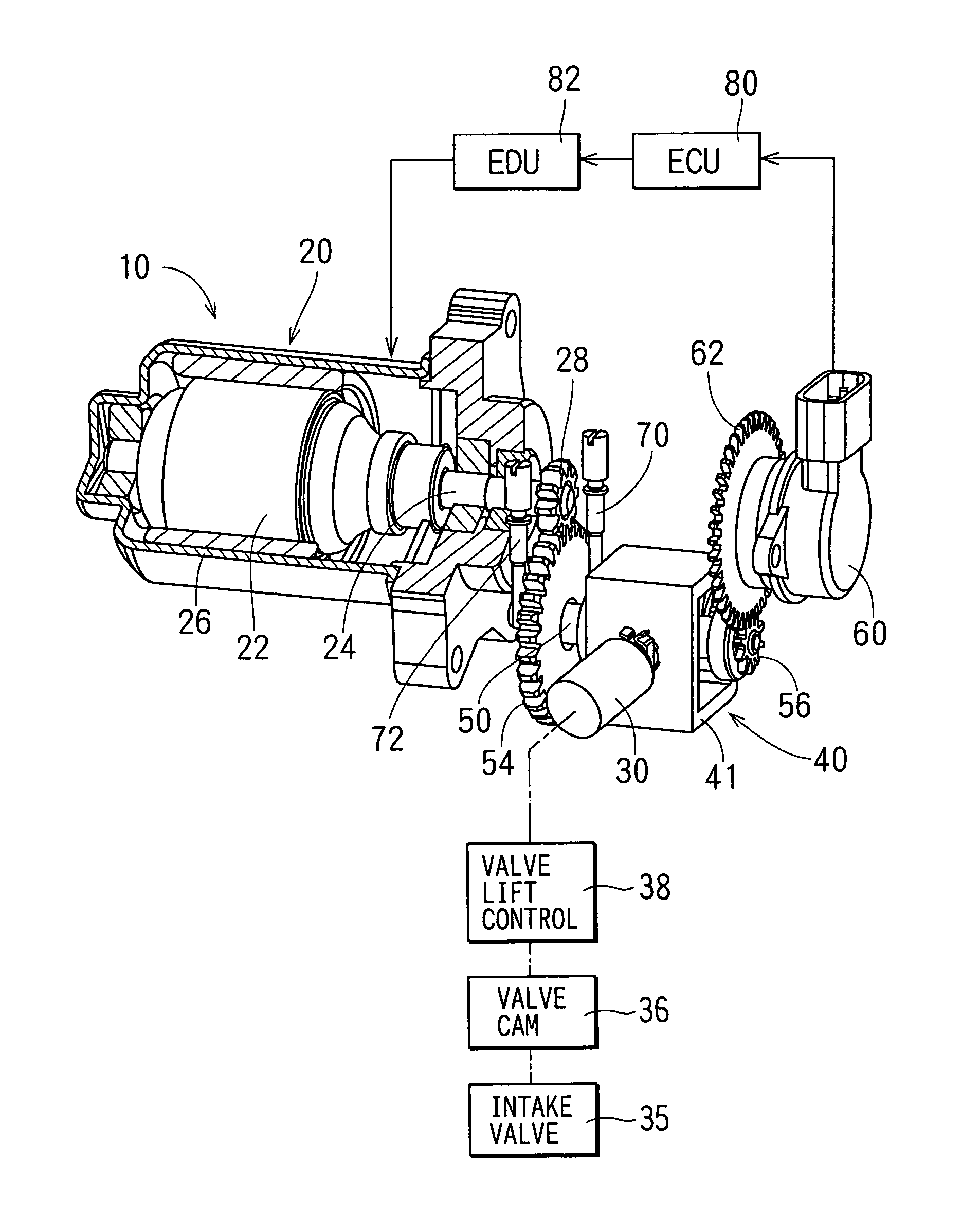
[0028]As shown in FIG. 1, an actuator 10 is used for actuating a valve lift controller 38 for an internal combustion engine, for example. Here, the valve lift controller 38 controls relative lift-difference between an intake valve 35 and a valve cam 36 of the engine in accordance with an axial position of a control shaft 30. The valve cam 36 opens and closes the intake valve 35.

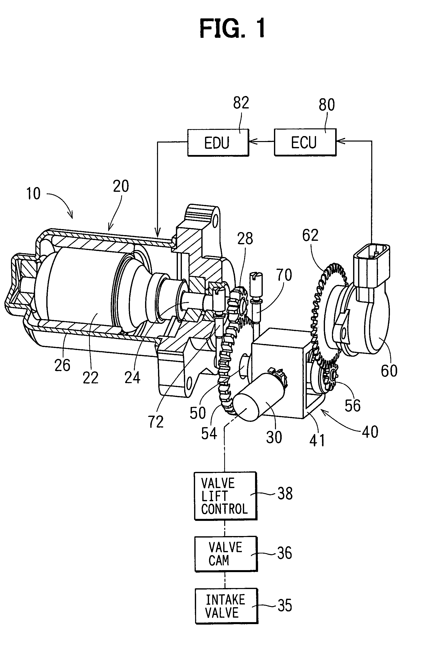
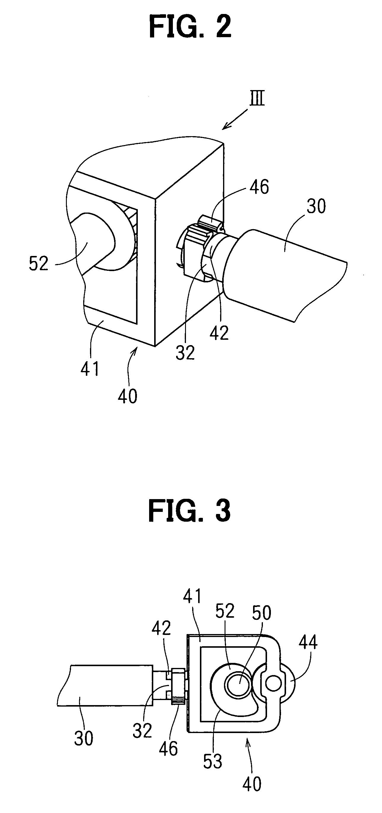
[0029]The actuator 10 includes a motor 20, the control shaft 30, a transmission device 40, a drive cam 52 (shown in FIG. 3), an angular sensor 60, an electronic control unit (ECU) 80, and an electronic drive unit (EDU) 82. The motor 20 is a DC motor including a rotor 22 having a winding coil and magnet 26 surrounding an outer periphery of the rotor 22. A motor gear 28 is provided on the axial end of a spindle 24 of the motor 20. The spindle 24 rotates with the rotor 22.

[0030]The control shaft 30 is joined with a supporting frame 41 of the transmission device 40 on its one end, and is joined ...

second embodiment

(Second Embodiment)

[0053]As shown in FIG. 9, an electromagnetic clutch 90 is provided on the motor 80 on the opposite end side of the motor gear 28 with respect to the spindle 24. The electromagnetic clutch 90 includes a rotating plate 91, a stator 92, a coil 94, an armature 96 and a blade spring 97. The rotating plate 91 is press-inserted onto the spindle 24 so as to be rotated with the spindle 24. The armature 96 is pressed onto the rotating plate 91 by the blade spring 97 when the coil 94 is de-energized. The blade spring 97 is partly locked by the stator 92. The rotation of the spindle 24 is restricted by friction between the armature 96 and the rotating plate 91 when the armature 96 is pressed onto the rotating plate 91 by the blade spring 97. That is, a rotation of the motor 80 is stopped when the coil 94 is de-energized. The armature 96 is pulled toward the stator 91 against pressing force of the blade spring 97 when the coil 94 is energized, so that the armature 96 is depart...


PUM


Abstract

An actuator is used for controlling an intake valve lift of an automotive engine. A control shaft is joined with a transmission device on its one end side, and is joined with a valve lift controller on the other end side. The control shaft is arranged perpendicularly to a spindle of a motor. Besides, the transmission device includes a drive cam internally. Thus, the actuator is reduced in size in a longitudinal direction of the control shaft regardless the length of the motor. When the motor rotates, the control shaft reciprocates in accordance with a cam profile of the drive cam. The intake valve lift can be precisely controlled by defining the cam profile, especially in a rotation range of the drive cam corresponding to the idling operation of the engine.

Description

CROSS REFERENCE TO RELATED APPLICATION[0001]This application is based on Japanese Patent Application No. 2002-315588 filed on Oct. 30, 2002 the disclosure of which is incorporated herein by reference.BACKGROUND OF THE INVENTION[0002]The present invention is related to an actuator for manipulating a controlled object in accordance with an axial position of a control shaft while transferring a rotation of a motor to a reciprocating motion of the control shaft, and a valve lift control system using the actuator.[0003]1. Related Art[0004]In an automotive engine, an actuator is used for manipulating a controlled object in accordance with an axial position of a control shaft.[0005]According to a variable valve mechanism for an internal combustion engine in U.S. Pat. No. 6,425,357 (JP-A-2001-263015), an intermediate driving mechanism is movably supported on its axis independent of the axis of a valve cam. The intermediate driving mechanism includes a control shaft, a valve cam related part...

Claims


Application Information

Patent Timeline
IPC IPC(8): F01L1/34F01L13/00F01L1/46F16H25/16
CPCF01L13/0005F01L13/0015F01L2820/032F01L2201/00F01L2105/00F01L2305/00
Inventor SHIBATA, AKIRASUZUKI, YASUYOSHI
Owner DENSO CORP
Why Eureka
Try Eureka