
Life safety alarm with a sealed battery power supply

Active Publication Date: 2005-04-28
WALTER KIDDE PORTABLE EQUIP
View PDF25 Cites 11 Cited by
  • Summary
  • Abstract
  • Description
  • Claims
  • Application Information

AI Technical Summary

Benefits of technology

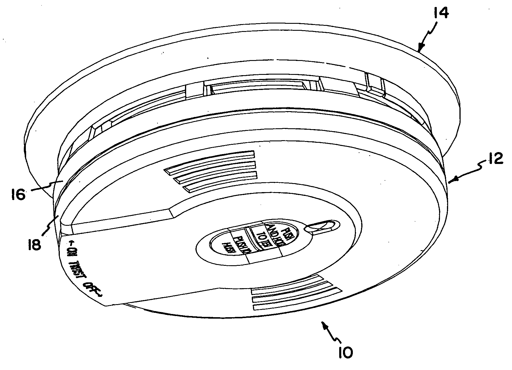
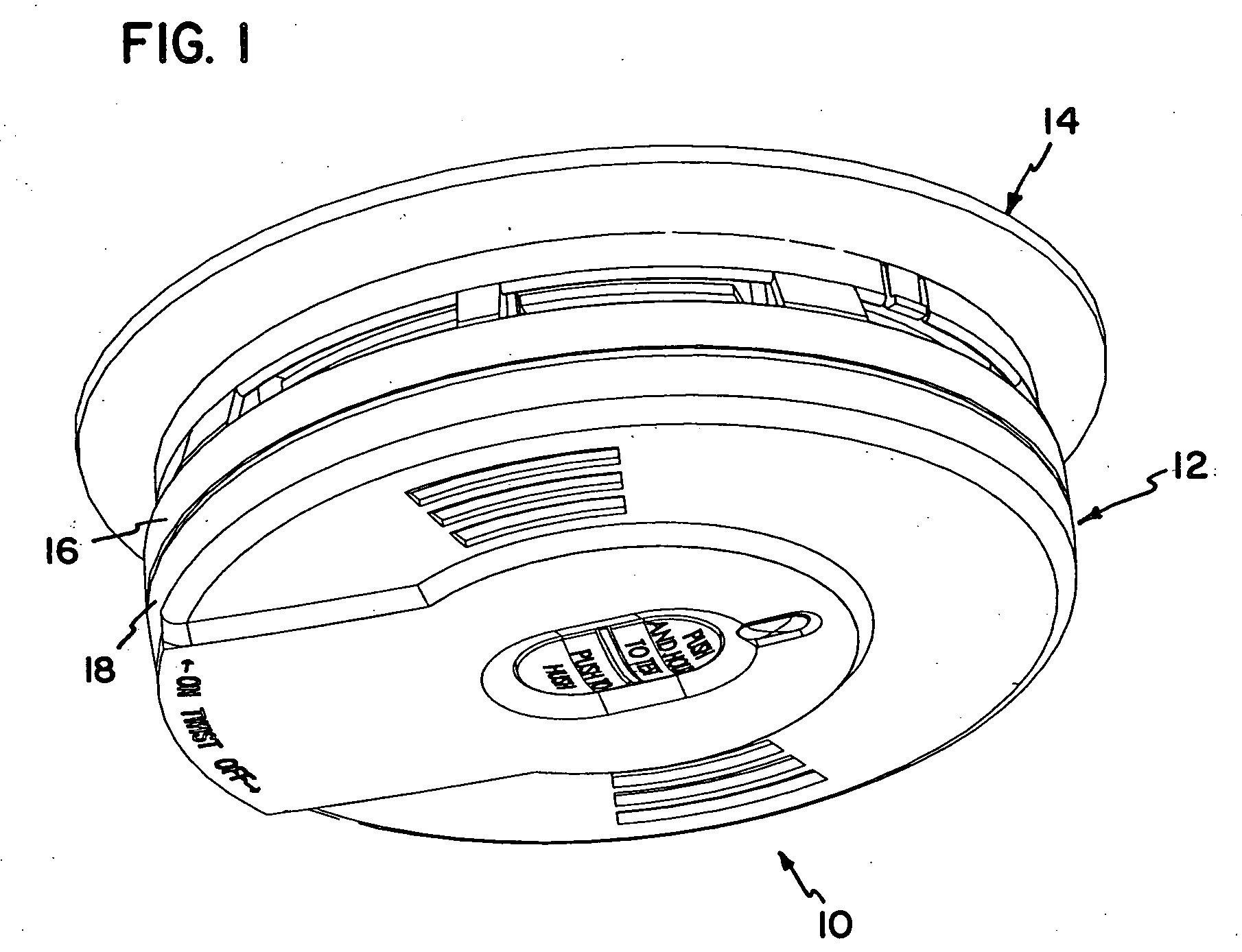
[0009] The invention relates to a life safety alarm that is battery powered and has an extended life. The invention further relates to a life safety alarm that is less prone to user mistakes. The batteries are sealed inside the alarm portion whereby the batteries cannot be accessed by the user. As a result, the batteries are not replaceable. Rather, the alarm portion is replaced at the end of the alarm life, for example after expiration of a predetermined time period. Because the batteries are not replaceable, the difficulties and mistakes that accompany battery replacement are eliminated.
[0010] The alarm preferably has a long life in order to reduce the time period between alarm body replacement. For example, in the preferred embodiment, the batteries and other alarm components are intended to have a life-span of ten years. The alarm could have other life-spans as well.
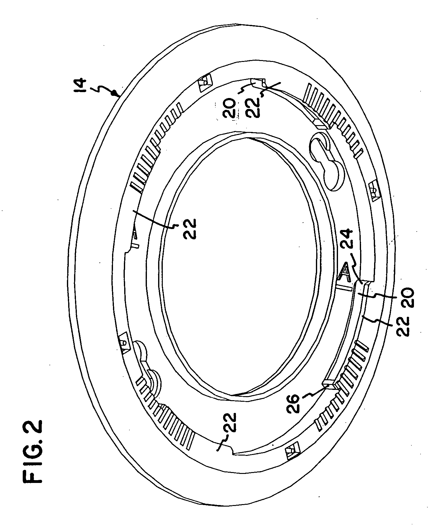
[0011] In addition, the alarm is designed to automatically activate when the user attaches the alarm portion to the mounting bracket. At the end of the alarm life, the alarm will emit a signal to indicate that the alarm portion needs replacement. The user then removes the alarm portion from the mounting bracket and slides a switch on the alarm to deactivate the alarm. Deactivation of the alarm removes power from the alarm circuitry and drains remaining power from the batteries. Further, when deactivated, the alarm portion is mechanically prevented from being mounted back on the mounting bracket.
[0012] Alarm activation is automatic, and no user interaction, other than attaching the alarm portion to the mounting bracket, is necessary in order to activate the alarm. Therefore, the user cannot mistakenly forget to activate the alarm. Further, the alarm is designed so that the user can only change the alarm from an ON condition to the DEACTIVATED condition. Once in the DEACTIVATED condition, the alarm cannot be changed back to the ON condition without breaking the alarm. However, even if the alarm is changed back to the ON condition after being deactivated, the alarm is designed to prevent reattachment of the alarm portion to the mounting bracket.

Problems solved by technology

As a result, the batteries are not replaceable.

Method used


Image

  • Life safety alarm with a sealed battery power supply
  • Life safety alarm with a sealed battery power supply
  • Life safety alarm with a sealed battery power supply

Examples


Embodiment Construction

[0026] The invention relates to a battery powered electronic device in which the batteries are sealed within the device to prevent access to the batteries by the user, whereby the batteries are not intended to be replaceable. For convenience, the inventive concepts will be described herein with respect to a life safety alarm, in particular a smoke alarm. However, it is to be realized that the inventive concepts could be applied equally as well to other life safety devices, for example a carbon monoxide alarm or a flame detector. In addition, for convenience, the smoke alarm will be described herein as having a plurality of batteries. However, it is to be realized that the inventive concepts described herein could be utilized in alarms having a single battery.

[0027] In general, the electronic device according to the invention includes a first portion, and a second portion configured for attachment to the first portion. The second portion includes electronics to operate the device an...


PUM


Abstract

A life safety alarm, for example a smoke alarm, that is battery powered, has an extended life, and is less prone to user mistakes. The batteries are sealed inside the alarm portion so that the batteries cannot be accessed by the user. As a result, the batteries are not replaceable. Rather, the alarm portion is replaced at the end of the alarm life, for example after expiration of a predetermined time period, such as ten years. The alarm is designed to be automatically activated upon initial attachment of the alarm portion to the bracket. The alarm can be manually deactivated, but once deactivated, the alarm cannot be reactivated and the alarm portion cannot be reattached to the bracket.

Description

PRIORITY DATA [0001] This application claims the benefit of U.S. Provisional Application No. 60 / 499,245 filed Aug. 29, 2003.FIELD OF THE INVENTION [0002] The invention relates to battery powered electronic devices. More particularly, the invention relates to battery powered electronic devices, especially life safety alarms, for example smoke alarms and carbon monoxide alarms, where the batteries are sealed inside the device to prevent access to the batteries. BACKGROUND OF THE INVENTION [0003] Electronic devices that are powered by one or more batteries are well known. These devices are often designed to permit installation of the batteries, as well as replacement of the batteries as needed. [0004] In certain battery powered electronic devices it is especially important that the batteries be properly installed and that the batteries have sufficient power for proper operation of the device. One example of such an electronic device is a battery powered life safety alarm. Life safety a...

Claims


Application Information

Patent Timeline
IPC IPC(8): G08B17/10G08B17/113G08B29/18
CPCG08B17/10G08B29/181G08B17/113
Inventor DELUCA, JOSEPH G.SHARPE, JASON M.
Owner WALTER KIDDE PORTABLE EQUIP
Learn More