Covering mechanism for a cold frame

Inactive Publication Date: 2015-05-07
LOONEY DONALD F
View PDF10 Cites 12 Cited by
  • Summary
  • Abstract
  • Description
  • Claims
  • Application Information

AI Technical Summary

Benefits of technology

[0021]The organized and uniform nature of the opening and closing of the covering also results in a dramatically extended useful life for the plastic covering. For example, the covering most commonly used today to cover cold frames is 4 mil polyethylene. This particular thickness of polyethylene is commonly referred to as “one-year film,” reflecting roughly how long it can be expected to last if it is used on a cold frame for one season (i.e. applied in the fall and removed in the spring). Using the system of the present invention, the plastic can be rolled up neatly and quickly when unneeded to avoid undue exposure to sunlight, which degrades the plastic. Accordingly, a feature of the present invention is that the life of the plastic covering can be dramatically extended. For example, because the plastic used in the present invention receives much less sun exposure, its useful life can be extended to two or three times the typical useful life, or more. In addition, because the plastic used with the present invent

Problems solved by technology

Invariably, the covering is light-transmitting although not necessarily light transparent and is most often “fixed”; that is, it remains in place and is not easily openable or removable.
However, cold frames can also cause problems for growing plants.
Also, because plants naturally grow toward the light—a tendency known as phototropism—and because cold frame coverings invariably attenuate the light, plants in cold frames can tend to be spindly.
Cold frames can be uncovered and recovered manually, of course, but the cost, time and labor associated with uncovering and recovering manually makes it impractical to do so frequently.
Moreover, when a cold frame is uncovered and the plastic is removed, the plastic often is abraded, pierced, and/or torn such that it cannot be used again.
Moreover, it is usually dirty and wrinkled making it unfit for

Method used


Image

  • Covering mechanism for a cold frame
  • Covering mechanism for a cold frame
  • Covering mechanism for a cold frame

Examples


Example

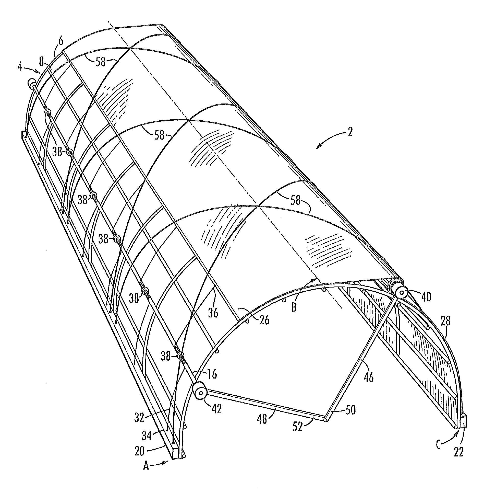
[0028]As described in summary form above, this invention relates to a covering mechanism for a cold frame, Although described in terms of its use with a cold frame, it will be clear that the covering mechanism can be used with other temporary or semi-permanent enclosures with little or no modification.

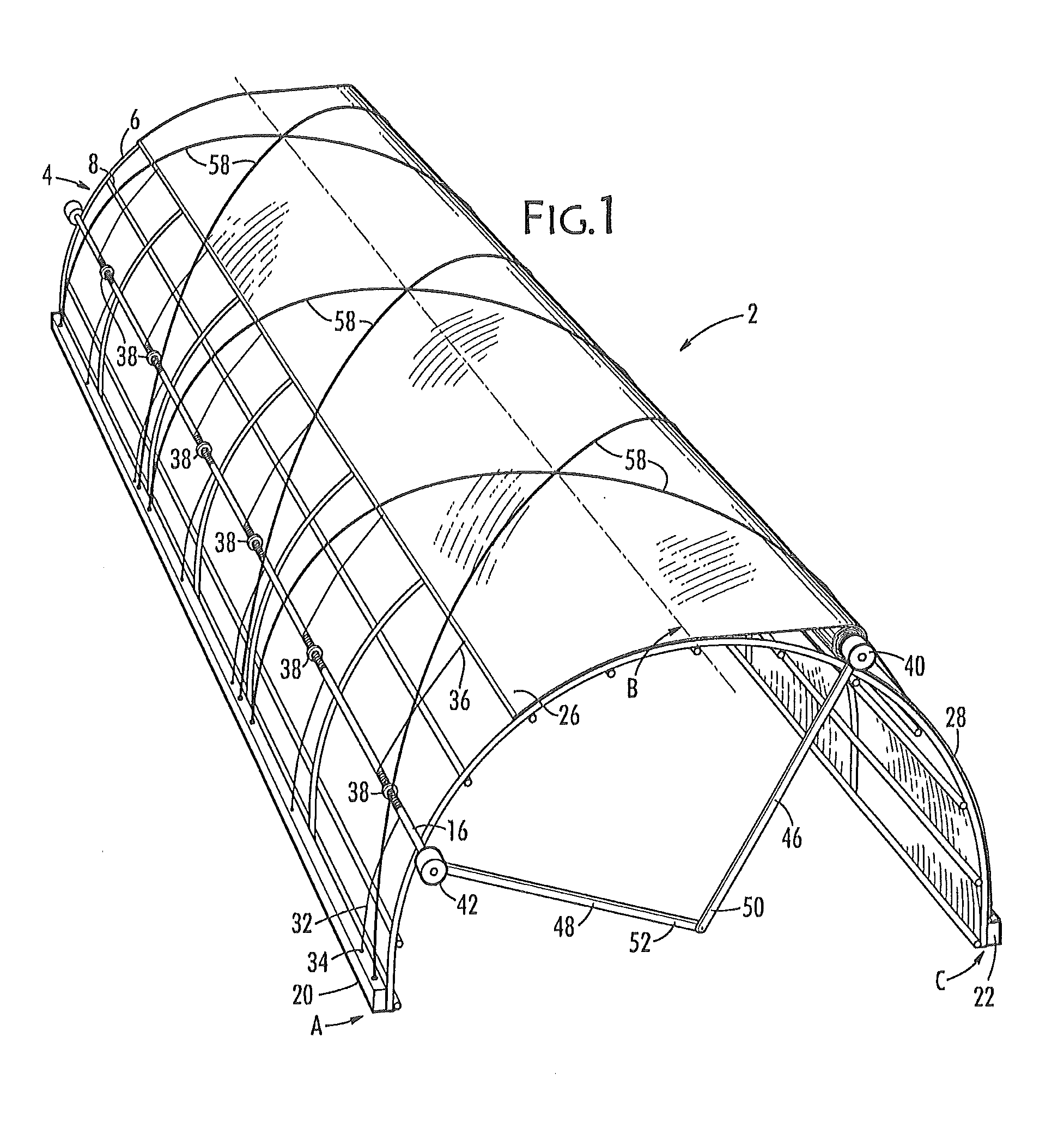
[0029]A cold frame is essentially a rounded structure, roughly forming a flattened half cylinder, made by combining a series of bowed members and purlins together to form a simple frame. The frame elements are typically made of tubular metal such as aluminum, and support a flexible, light-transmitting covering. The frame gives the cold frame its characteristic shape and serves to define the roof and walls of the cold frame. The bowed members, which are affixed at their bases to a foundation, and purlins, are further supported at the ends of the cold frame by vertical end members.

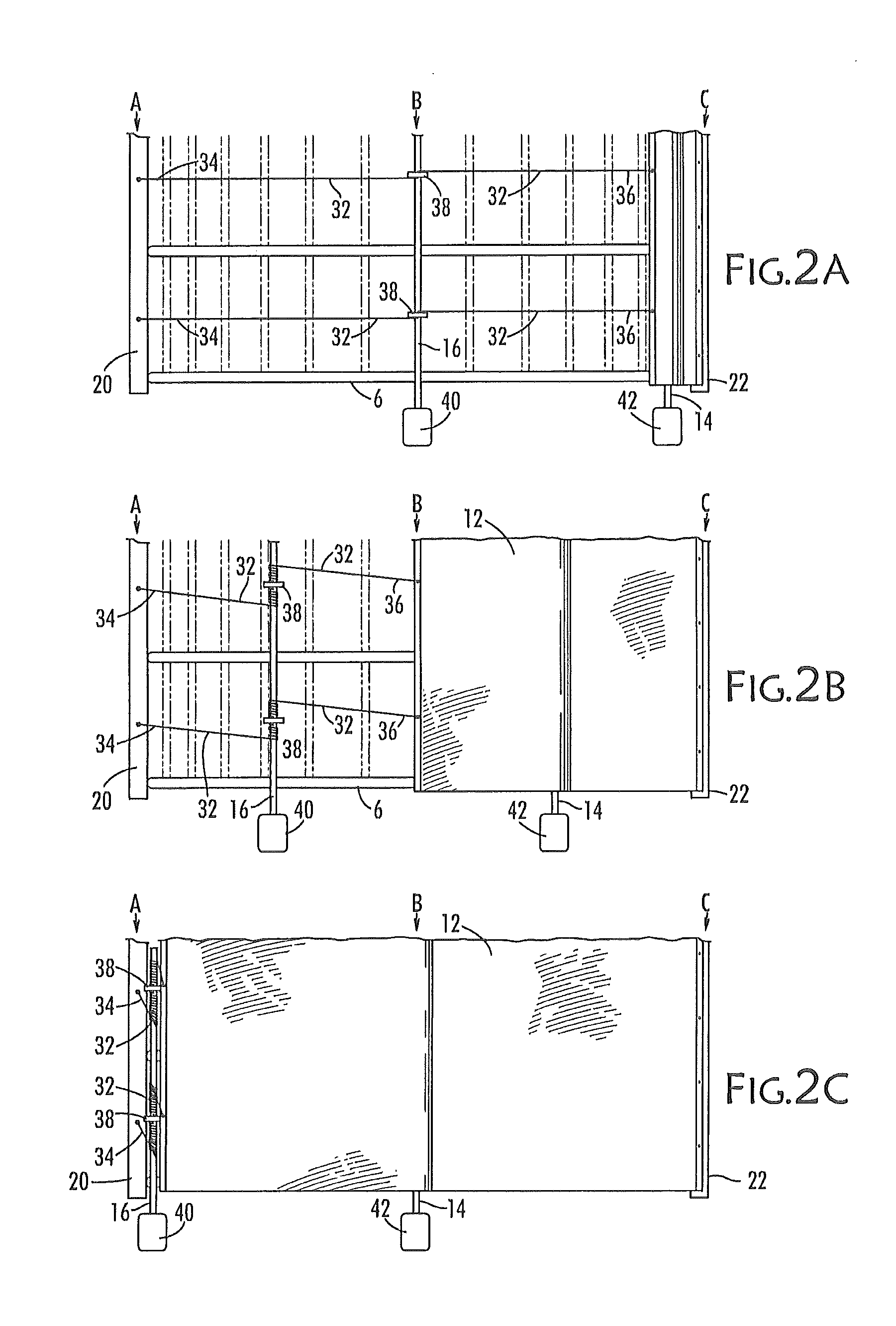
[0030]A cold frame according to one embodiment of the present invention is illustrated in FIGS. 1, 2A-C, and...


PUM


Abstract

A mechanism for covering and uncovering a cold frame includes a starting base and a spaced-apart terminal base, a frame, and a cover deployable over the frame starting at the starting base and ending at the terminal base. The cover is wrapped from its midline around a cover shaft rotated by a first drive motor, as cables, attached to the leading edge of the cover, pull it over the frame. Those cables are simultaneously winding themselves around a cable shaft rotated by a second drive motor so that cover remains tight between the cable shaft and the cover shaft. The other end of the cables is secured to the starting base while the trailing edge of the cover is secured to the terminal base. Torque arms extend from the first and second drive motors and their distal ends are pivotally connected.

Description

CROSS REFERENCE TO RELATED APPLICATIONS[0001]None.STATEMENT REGARDING FEDERALLY SPONSORED RESEARCH OR DEVELOPMENT[0002]Not applicable.REFERENCE TO A SEQUENCE LISTING, A TABLE, OR A COMPUTER PROGRAM LISTING COMPACT DISC APPENDIX[0003]Not Applicable.BACKGROUND OF THE INVENTION[0004]The present invention relates generally to cold frames. More specifically, the present invention relates to devices that allow the user to cover and uncover a cold frame at will.[0005]A cold frame is a lightweight enclosure that provides covering for plants and seedlings, whether planted in flowerpots or trays or in the earth enclosed by the cold frame. Typically, a cold frame comprises a framework and a covering. The framework can be made of metal, wood or plastic; and the covering is typically made of plastic sheeting (e.g., transparent polyethylene). Invariably, the covering is light-transmitting although not necessarily light transparent and is most often “fixed”; that is, it remains in place and is not...

Claims


Application Information

Patent Timeline
IPC IPC(8): A01G9/24A01G13/00
CPCA01G13/0206A01G9/242A01G13/0231Y02A40/25
Inventor LOONEY, DONALD F.
Owner LOONEY DONALD F
Why Eureka
Try Eureka