Solid-state imaging device, driving method thereof, and camera

a solid-state imaging and driving method technology, applied in the direction of color signal processing circuits, television systems, radio control devices, etc., can solve the problems of user perception of deterioration in moving pictures more than, straight lines appear as aliases, etc., to reduce noise, speed up frame frequency, and facilitate transfer driving

Active Publication Date: 2008-01-24
PANNOVA SEMIC
View PDF8 Cites 38 Cited by
  • Summary
  • Abstract
  • Description
  • Claims
  • Application Information

AI Technical Summary

Benefits of technology

[0021]With the structure, the hold unit which independently holds and transfers charges is formed between (i) the horizontal transfer unit and (ii) each of the vertical transfer units in columns each of which is a column in N columns except M columns in each column group, so that the transfer driving becomes easy which is suitable for speeding up a frame frequency.
[0022]Still further, the solid-state imaging device may further include: a memory operable to store data representing each of packets included in at least one row, the packets being outputted from the horizontal transfer unit; and a subtraction processing unit operable to reduce noise by performing subtraction processing using a first mixed packet and a second mixed packet, the first mixed packet being outputted from the horizontal transfer unit, and the second mixed packet being stored in the memory, wherein the first mixed packet is a packet in which the signal packet and the plurality of the dummy pac

Problems solved by technology

The above solution, however, has a problem that, when smears occur in an image of a light source imaged by extreme light intensity, for example, smear edges which

Method used


Image

  • Solid-state imaging device, driving method thereof, and camera
  • Solid-state imaging device, driving method thereof, and camera
  • Solid-state imaging device, driving method thereof, and camera

Examples


first embodiment

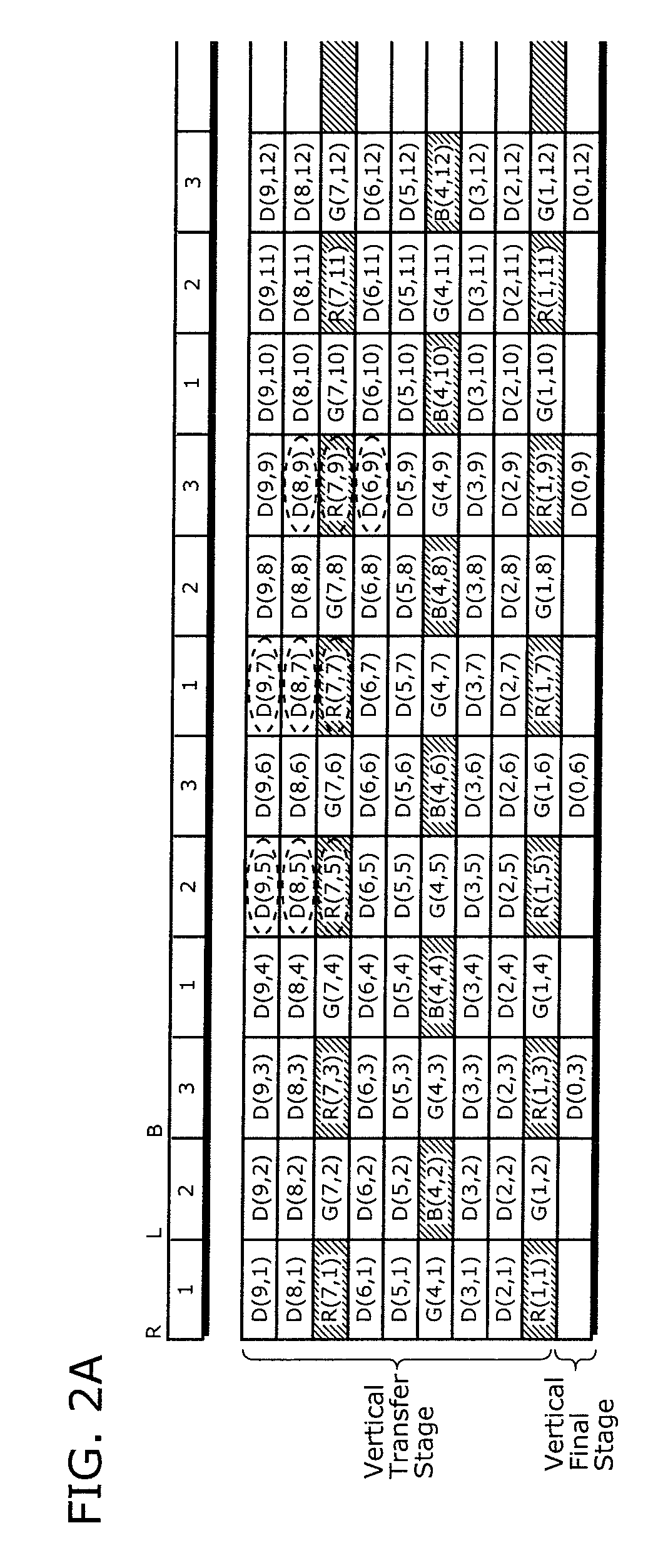
[0066]A solid-state imaging device according to the first embodiment includes a plurality of hold units which are arranged for final stages of the vertical transfer units in N columns except M columns (where M is the number equal to or more than 1, and in the embodiments M is 1 as one example) in the column group, and each of which is operable to mix, hold, and vertically transfer charges of the signal packets and the dummy packet without depending on vertical transfer from upstream of the corresponding vertical transfer unit. In a moving picture imaging mode, the hold unit mixes charges of a signal packet and neighboring dummy packets in an identical column together into a mixed packet, and holds the resulting mixed packet. The horizontal transfer unit further mixes such a mixed packet with other packets. Here, the “signal packet” refers to a vertical transfer stage including signal charges read out from a light-receiving element, and the “dummy packet” refers to an originally empt...

second embodiment

[0104]The following describes a solid-stage imaging device according to the second embodiment. According to the second embodiment, any final stages of the vertical transfer units 13 do not have independent transfer electrodes. In addition, the hold units in the first embodiment are replaced to hold units which are formed between the horizontal transfer unit 14 and respective vertical transfer units 13 in predetermined columns. Here, each of the predetermined columns is a column in N columns except M columns (where M is 1, for example) in each column group. The column group has N columns and such a column group is repeated in a horizontal direction. As a result, the hold units hold and transfer charges independently in every N other columns.

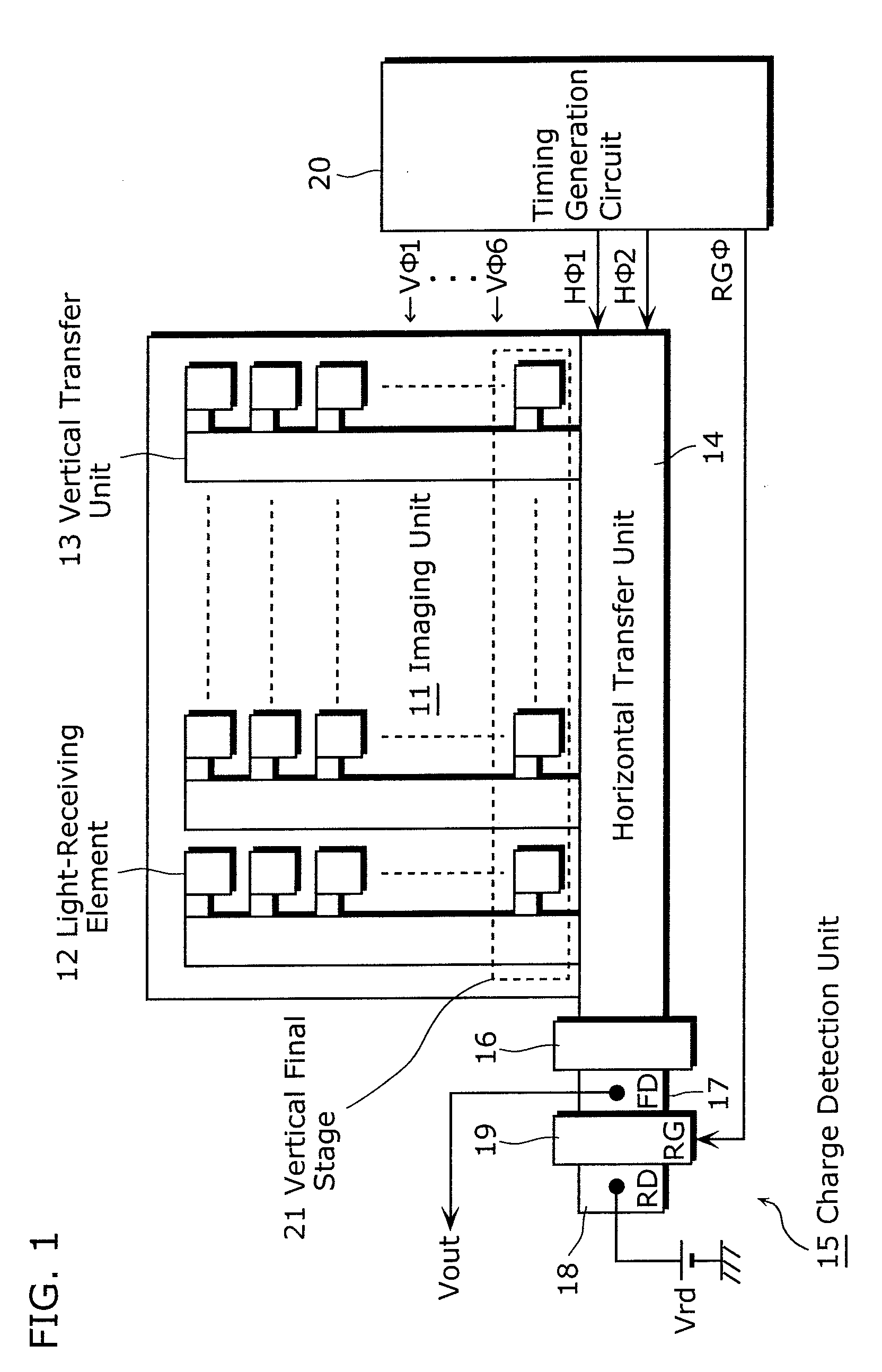
[0105]FIG. 4 is a block diagram showing a structure of the solid-state imaging device according to the second embodiment of the present invention. The structure of FIG. 4 differs from the structure of FIG. 1 in that the final stages 21 of all vert...

third embodiment

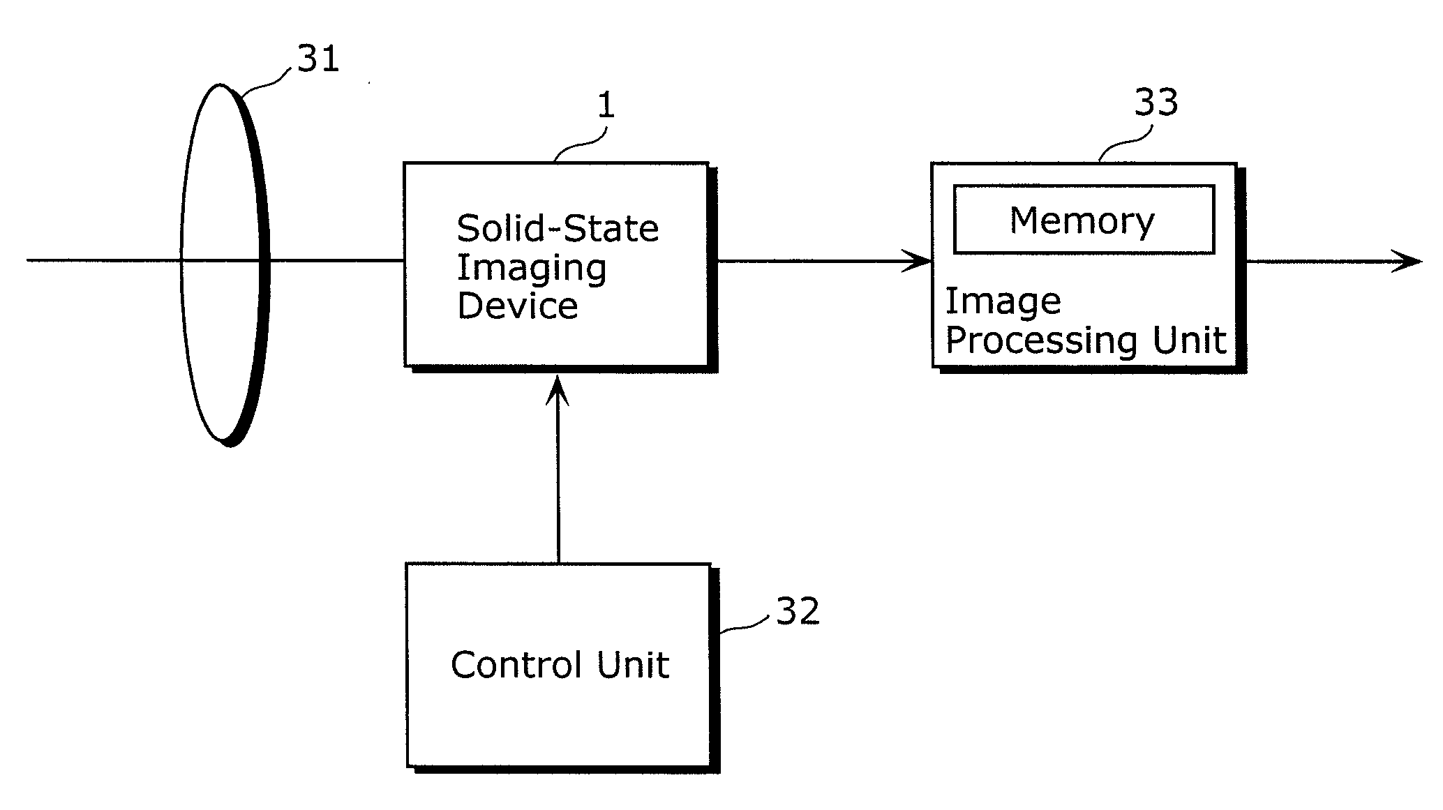
[0134]The following describes the third embodiment of the present invention. In the third embodiment, the processing of subtracting noise such as smears is performed in a structure of a camera in which the solid-stage imaging device according to the first and second embodiments is embedded. In the solid-stage imaging device according to the first and second embodiments, a column of a packet having noise components such as smears (hereinafter, referred to as “the second mixed packet”) is identical to a column of a signal packet having valid pixel signals (hereinafter, referred to as “the first mixed packet”). In the third embodiment, the second mixed packet is obtained by storing, in a memory, noise components such as smears included in signals of a vertical optical black (OB) pixel, a vertical dummy pixel, a vertical empty transfer packet, and the like. An amount of the stored noise components is regarding one row or more. Then, subtraction is sequentially performed for horizontal t...


PUM


Abstract

A solid-state imaging device includes: a plurality of light-receiving elements which are arranged by rows and columns; a plurality of vertical transfer units each of which is arranged for a corresponding column of the light-receiving elements, and vertically transfers a plurality of signal packets and dummy packets, the signal packet including charges read from the light-receiving elements, the dummy packets being packets other than the signal packets, and N columns of the vertical transfer units forming one column group; a plurality of hold units which are arranged for final stages of the vertical transfer units in N columns except M column in the column group, and each of which mixes, holds, and vertically transfers charges of the signal packets and the dummy packet without depending on vertical transfer from upstream of the corresponding vertical transfer unit; a horizontal transfer unit which mixes, holds, and horizontally transfers the charges transferred from the hold units or the vertical transfer units in the M column in the column group; and a driving unit which drives the vertical transfer units, the hold units, and the horizontal transfer unit, wherein the driving unit perform the driving, so that a signal packet and a plurality of dummy packets in an identical column are mixed together into a mixed packet in each of the holding units, charges of the mixed packet are held in the hold unit, the held charges of the mixed packet are vertically transferred to the horizontal transfer unit so that the mixed packet is mixed with a mixed packet of a different hold unit which is vertically transferred from the different hold unit to the horizontal transfer unit.

Description

BACKGROUND OF THE INVENTION[0001](1) Field of the Invention[0002]The present invention relates to: a solid-state imaging device which includes two-dimensionally arranged light-receiving elements, vertical transfer units, and a horizontal transfer unit, and outputs image signals; a driving method of the device; and a camera using the device, and particularly to a solid-state imaging device having a still picture imaging mode and a moving picture imaging mode; a driving method of the device; and a camera using the device.[0003](2) Description of the Related Art[0004]Charge-Coupled Device (CCD) imaging sensors have been known as solid-state imaging devices each of which has a plurality of light-receiving elements for converting incident light into electrical charges and outputs the charges as image signals. Furthermore, digital still cameras using such solid-state imaging devices have become popular. In recent years, technologies of high pixel density in solid-state imaging devices hav...

Claims


Application Information

Patent Timeline
IPC IPC(8): H04N3/14H01L27/148H04N5/335H04N5/347H04N5/359H04N5/3728H04N5/376H04N9/07
CPCH04N5/3458H04N9/045H04N5/3728H04N25/73H04N25/447H01L27/148H04N25/62
Inventor KATO, YOSHIAKI
Owner PANNOVA SEMIC
Why Eureka
Try Eureka