Disk Device

Inactive Publication Date: 2008-01-24
CLARION CO LTD
View PDF9 Cites 0 Cited by
  • Summary
  • Abstract
  • Description
  • Claims
  • Application Information

AI Technical Summary

Benefits of technology

[0010] The present invention is, therefore, contrived in order to resolve the above problems of the conventional technology, and an object of the present invention is to provide a disk device which is capable of reliably guiding and housing disks into disk housing sections in a small required space.

Problems solved by technology

Therefore, the walls of the magazine main body are thick, and as a result the sizes of the magazine itself and the entire device for installing the magazine are large.
In addition, in order to take out a disk housed in the magazine and play the disk, it is necessary to provide a sufficient space in the device, thus the size of the device increases.
However, if the member for holding the disk on the disk housing section side is comparatively firm, the disk needs to be pushed in against this member, thus change of the course of the disk may not be enough to deal with this case.
Therefore, the tray is usually provided with a member for holding the disk, but when the trays move up and down in order to be split from one another, the disk may come out easily, thus the member in the tray may not be sufficient for holding the disk.
At this moment, however, the disk held in the tray also moves due to the up-and-down movement of the tray, thus it is difficult to directly contact with the disk to prevent it from coming out of the tray.
However, since the space around the disk is narrow, it is not easy to dispose these members without interrupting the movement of the disk.

Method used


Image

  • Disk Device
  • Disk Device
  • Disk Device

Examples


Embodiment Construction

[0080] Hereinafter, an embodiment (“present embodiment”, hereinafter) of an on-board disk device to which the present invention is applied is described in detail with reference to the drawings. It should be noted that, in the following descriptions of the drawings, the front face side of the disk device is the head side, the back face side of same is the rear side, and the vertical and longitudinal directions correspond to the directions viewed from the front face side of the disk device.

A. Entire Configuration

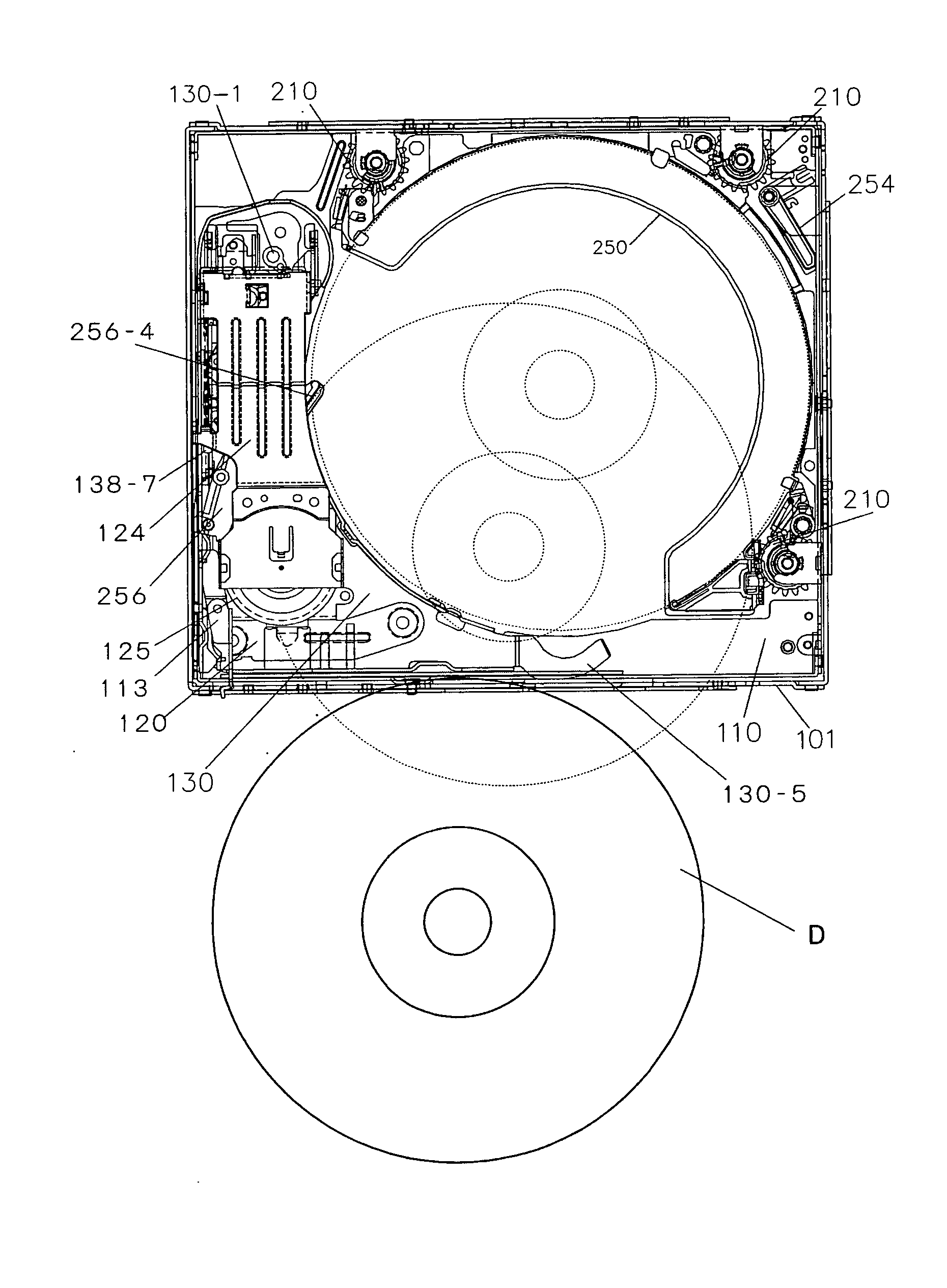
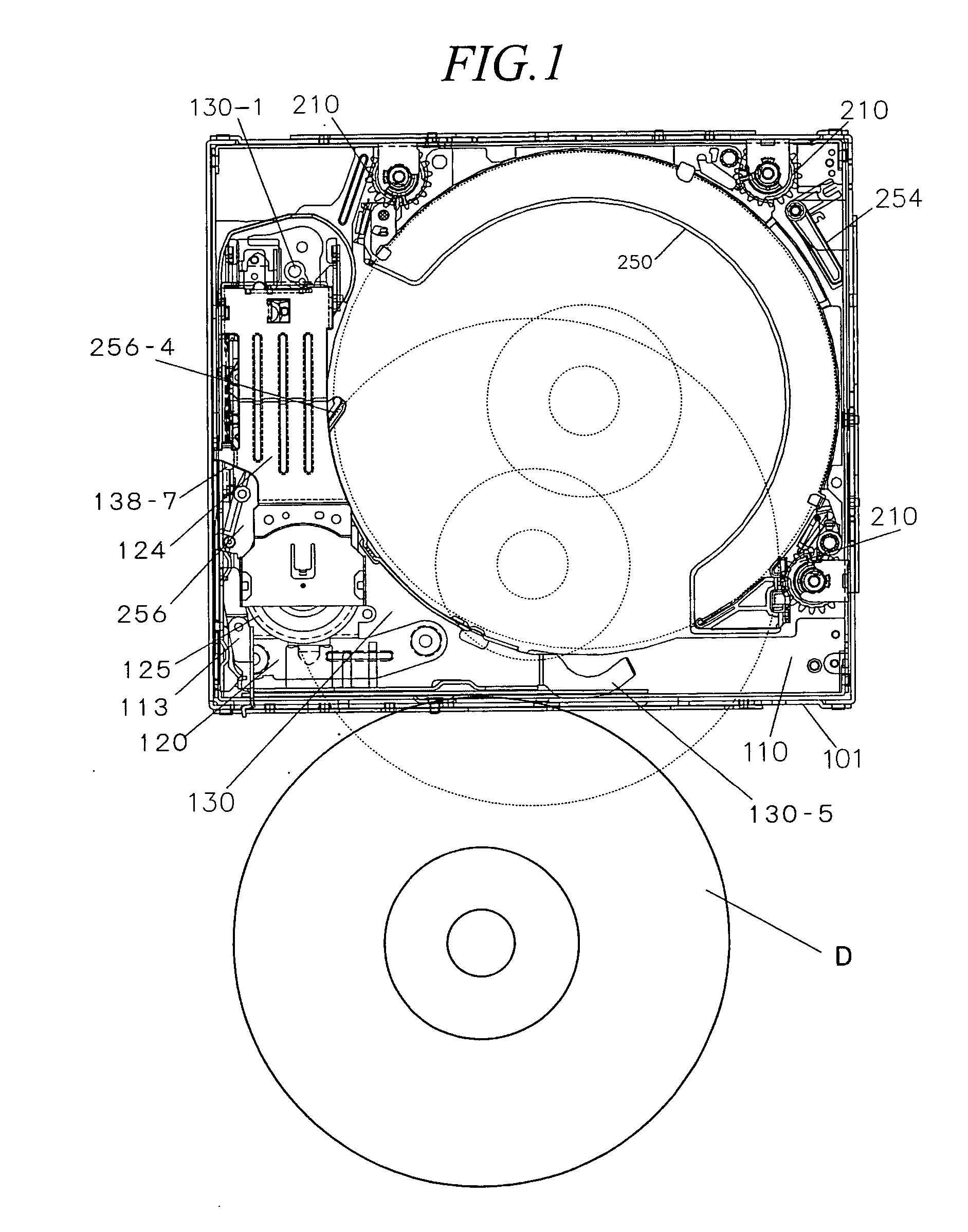
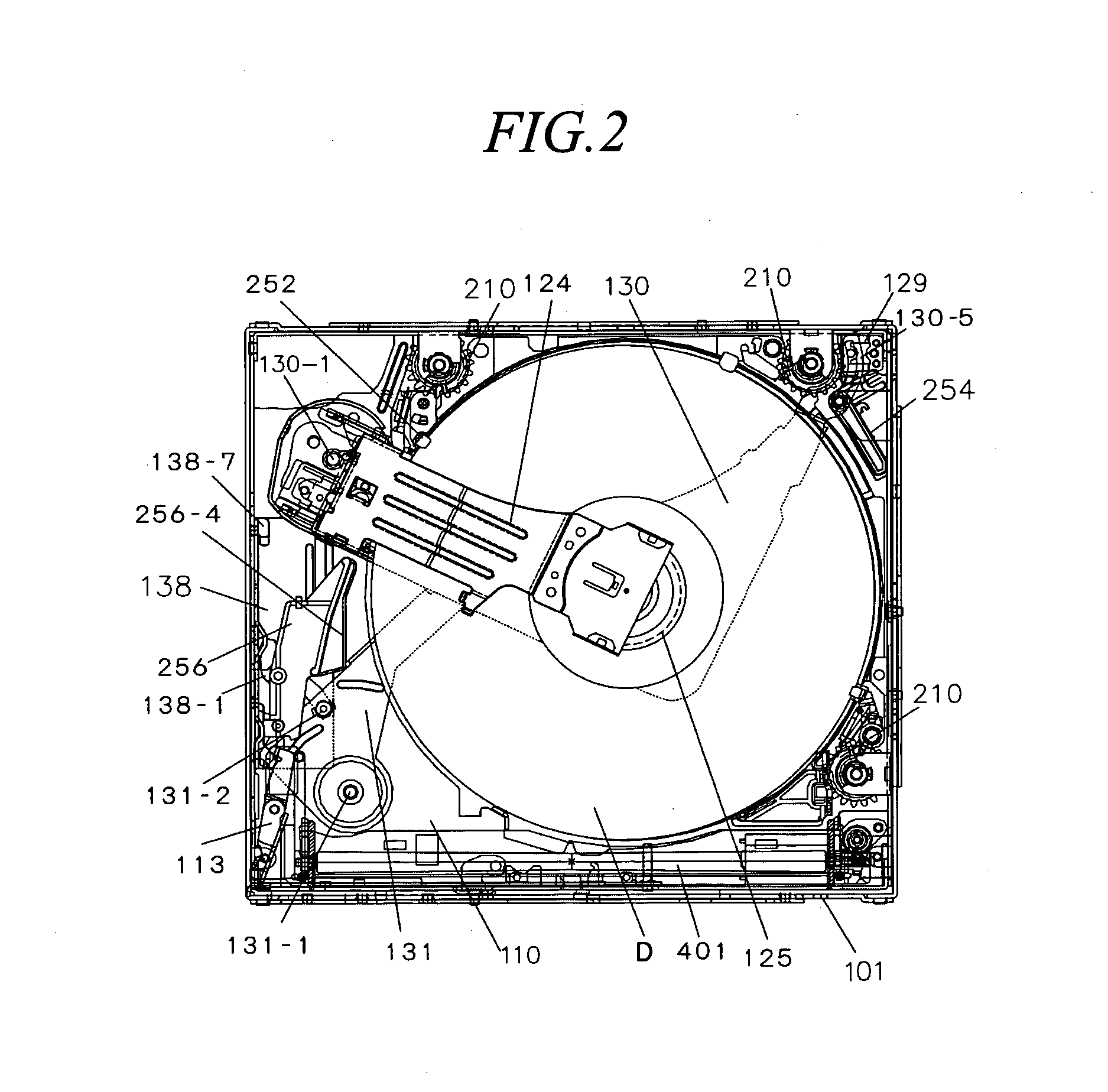
[0081] The present embodiment has the following schematic configurations as shown in FIG. 1, FIG. 2, FIG. 8, and FIG. 9:

[0082] (1) A pick chassis 110, in which trays 250 capable of holding disks D are stacked and which can move up and down in a chassis 101.

[0083] (2) A pick arm 130 which is swung to be inserted between split trays 250 (corresponding to the swing arm described in the claims).

[0084] (3) A drive chassis 120 which is provided on the pick arm 130 and comprises...


PUM


Abstract

To provide a disk device, which can reliably lead and house a disk into a disk housing section requiring only a small space. The disk device is provided with: a pick arm 130 which swings and inserts a drive unit for playing a disk D into a space created by splitting a plurality of trays 250; and a loading arm 256 which can move between a leading position for abutting on the disk D inserted / ejected with respect to the tray 250 and leading the disk D, and a withdrawing position for withdrawing from the disk to be played. A pick swing cam plate 138, which controls the drive of the pick arm 130 and the loading arm 256, is provided so as to be slidingly moved by a drive mechanism.

Description

TECHNICAL FIELD [0001] The present invention relates to the improvement of a disk device, which splits disk housing sections housing a plurality of disks therein and moves a drive unit playing a disk to a space formed between the split disk housing sections, to play a disk. BACKGROUND ART [0002] Conventionally, there has been widely used a disk device which is installed with a magazine for housing disks and in which a disk taken out from the magazine is automatically played. Such a disk device is excellent in operability since the disks do not have to be inserted or ejected one by one every time when playing the disk. [0003] However, it is required that the magazine attached or detached with respect to the device be strong enough to protect a plurality of disks held therein when taking out the magazine to the outside. Therefore, the walls of the magazine main body are thick, and as a result the sizes of the magazine itself and the entire device for installing the magazine are large....

Claims


Application Information

Patent Timeline
IPC IPC(8): G11B17/22G11B17/26
CPCG11B17/225G11B17/021
Inventor HANDA, HIROTOTAKAHASHI, AKIRA
Owner CLARION CO LTD
Why Eureka
Try Eureka