System for Depth Control of a Marine Deflector

a technology of depth control and deflector, which is applied in the field of system for controlling the depth of a seismic deflector, can solve the problems of rope, safety chain, and deflector devices in current use being very large, and may break

Inactive Publication Date: 2008-01-31
WESTERNGECO LLC
View PDF7 Cites 39 Cited by
  • Summary
  • Abstract
  • Description
  • Claims
  • Application Information

AI Technical Summary

Benefits of technology

[0027]The present invention thus makes it possible to vary the depth of a deflector while the deflector is deployed. The depth of a deflector can be varied without varying the lateral position of the deflector (that is, without varying the lateral distance between the deflector and the central axis that extends directly behind the towing vessel).

Problems solved by technology

The MONOWING deflector devices in current use are very large, typically 7.5 m high by 2.5 m wide, and weigh several tons.
If the wing-shaped body then drops abruptly, the rope, and possibly even the safety chain, may break, and / or their attachment points on the wing-shaped body may be badly damaged.
As a result of this, the operating depth of the deflector device cannot readily be varied while the device is deployed in the water.
And since the normal operating depth of the current deflector device is typically a few meters, in the event of the onset of bad weather during a survey, the device and all the streamers and other equipment directly or indirectly attached to it have to be recovered onto the towing vessel, and then re-deployed when the bad weather has passed, both of which operations are very time consuming.

Method used


Image

  • System for Depth Control of a Marine Deflector
  • System for Depth Control of a Marine Deflector
  • System for Depth Control of a Marine Deflector

Examples


Embodiment Construction

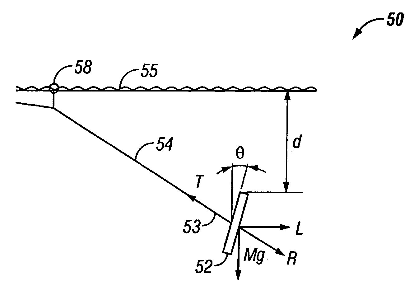
[0038]The present invention provides a marine deflector for a seismic survey system. The deflector has a generally upright deflector body that controllably tilts about an axis that is generally transverse to a cable that pulls the deflector through the water. In one embodiment, an adjustable bridle is coupled to the deflector body, wherein the adjustable bridle includes a connector for coupling the bridle to the cable, such as a lead-in, and wherein the adjustable bridle is capable of varying the tilt angle of the deflector body. The depth of the deflector body is controlled by varying the tilt angle of the deflector body. Preferably, the tilt angle is varied by pivoting the deflector relative to an axis that is generally transverse to the cable.

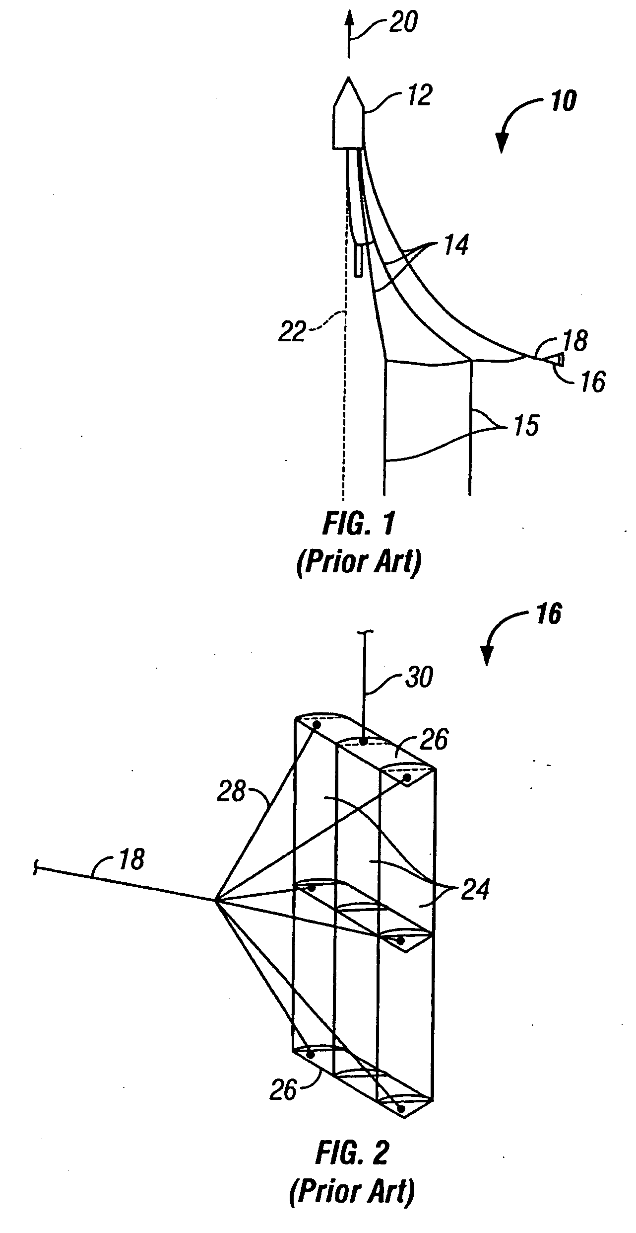
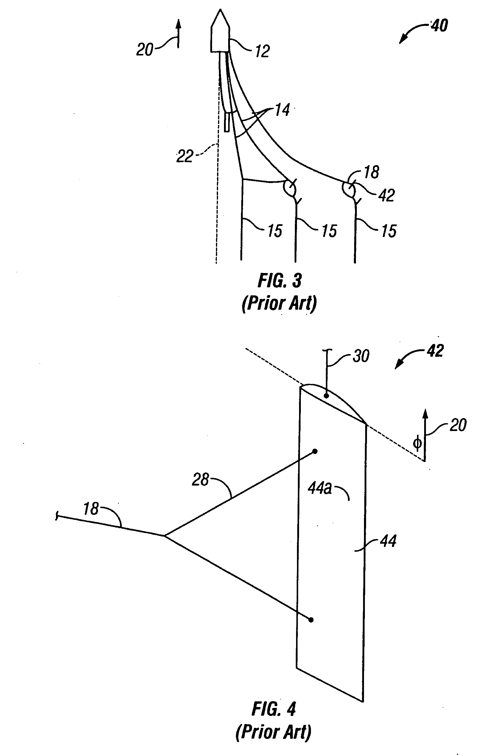
[0039]The deflector may comprise a so called wing deflector, e.g. the WesternGeco Monowing, or it may comprise a so called deflector door, frequently called a door or a Barovane comprising a series of hydrofoils mounted within a rectangular ...


PUM


Abstract

A system for adjusting a deflector in a seismic survey comprises a generally upright deflector body and at least one bridle connected to a seismic cable. The bridle includes an upper segment secured to an upper connection point on the deflector body, and a lower segment coupled to a lower connection point on the deflector body. The upper bridle segment, lower bridle segment and deflector body define a geometry between themselves. This geometry is adjustable by at least one actuator so as to control the tilt angle of the deflector body

Description

BACKGROUND OF THE INVENTION[0001]1. Field of the Invention[0002]The present invention relates to a system for controlling the depth of a seismic deflector under tow through the water.[0003]2. Background of the Related Art[0004]The ability to conduct accurate seismic surveys may help improve the discovery rates and even the production of subsurface accumulations, such as hydrocarbons. Seismic surveying is a method of stimulating a geological subsurface formation with, e.g., electrical, magnetic, and / or acoustic signals to acquire seismic data about the formation. From this data, one can predict whether the formation contains hydrocarbon deposits and, if so, where those hydrocarbon deposits are located.[0005]One type of seismic survey is generally referred to as a “marine” survey, because it is typically conducted at sea, although this is not necessarily always the case. During marine seismic surveys, seismic cable systems are deployed in the water behind a towing vessel.[0006]Deflect...

Claims


Application Information

Patent Timeline
Patent Type & Authority Applications(United States)
IPC IPC(8): B63G8/04A01K73/05B63B21/66G01V1/38
CPCA01K73/05G01V1/3826B63B21/663B63B21/66G01V1/38G01V1/3808
Inventor TOENNESSEN, RUNEKESKES, EMMANUELSTORTEIG, ESKILDHELGERUD, PERMOOSAVI, VAHIDSAINT-PERE, PHILIPPE
Owner WESTERNGECO LLC
Why Eureka
Try Eureka