Seismic Cable Positioning Using Coupled Inertial System Units

a technology of inertial system unit and seismic cable, which is applied in seismology, seismology, instruments, etc., can solve the problems of many factors and the high frequency of objects moving and determining the position of sensors

Inactive Publication Date: 2008-10-16
WESTERNGECO LLC
View PDF10 Cites 60 Cited by
  • Summary
  • Abstract
  • Description
  • Claims
  • Application Information

AI Technical Summary

Problems solved by technology

Marine surveys, however, are more dynamic, and sources, sensors and other objects move at a much higher frequency due to environmental conditions more difficult to control.
In both cases, many factors complicate determining the posit

Method used


Image

  • Seismic Cable Positioning Using Coupled Inertial System Units
  • Seismic Cable Positioning Using Coupled Inertial System Units
  • Seismic Cable Positioning Using Coupled Inertial System Units

Examples


Embodiment Construction

[0023]Illustrative embodiments of the invention are described below. In the interest of clarity, not all features of an actual implementation are described in this specification. It will of course be appreciated that in the development of any such actual embodiment, numerous implementation-specific decisions must be made to achieve the developers' specific goals, such as compliance with system-related and business-related constraints, which will vary from one implementation to another. Moreover, it will be appreciated that such a development effort, even if complex and time-consuming, would be a routine undertaking for those of ordinary skill in the art having the benefit of this disclosure.

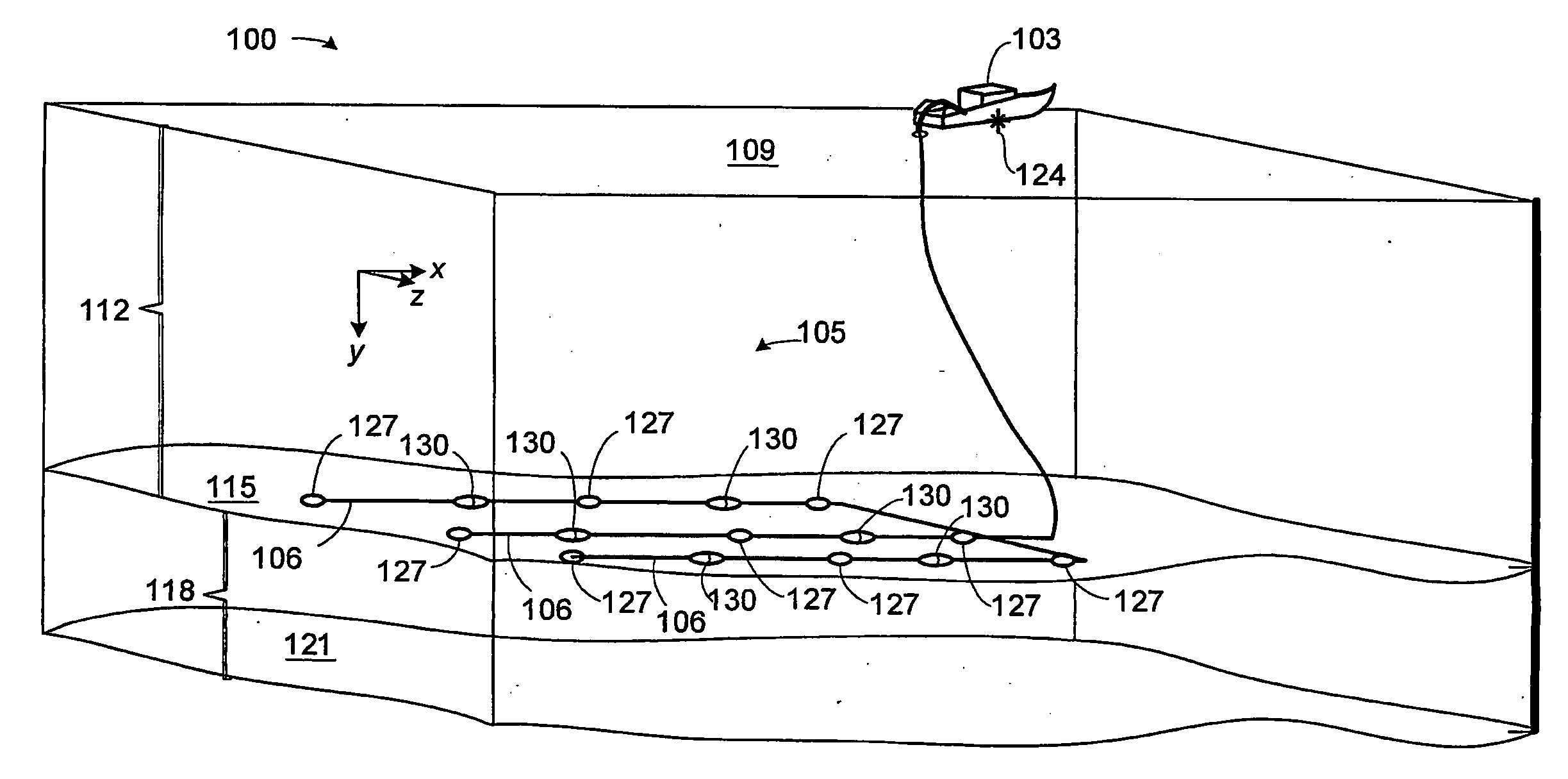
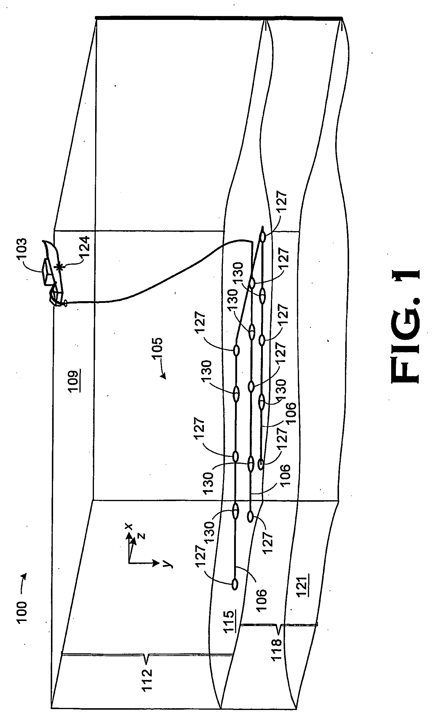
[0024]FIG. 1 is a three-dimensional, perspective view of a first seismic survey 100, in which a survey vessel 103 has deployed a seismic spread 105. The seismic spread 105 includes a plurality of seismic cables 106 in accordance with the present invention. The seismic cables 106 have been deploye...


PUM


Abstract

An apparatus and a method of its use in a marine seismic survey are disclosed. The apparatus includes a seismic survey object (106) and an inertial measurement device (130) coupled to the seismic survey object (106). The method includes taking inertial measurements of the movement of selected points on a seismic spread relative to at least one known point, and applying the inertial measurements to the known point to determine the positions of the selected points.

Description

BACKGROUND OF THE INVENTION[0001]1. Field of the Invention[0002]The invention pertains to seismic surveying and, more particularly, to a method and apparatus for more accurately determining the position of seismic survey objects in a marine seismic survey.[0003]2. Description of the Related Art[0004]Seismic exploration is conducted on both land and in water. In both environments, exploration involves surveying subterranean geological formations for hydrocarbon deposits. A survey typically involves deploying acoustic source(s) and acoustic sensors at predetermined locations. The source(s) imparts acoustic waves into the geological formations. Features of the geological formation reflect the acoustic waves to the sensors. The sensors receive the reflected waves, which are the processed to generate seismic data. Analysis of the seismic data may then indicate probable locations of the hydrocarbon deposits.[0005]Accurate knowledge of the positions of the seismic survey objects, e.g., aco...

Claims


Application Information

Patent Timeline
IPC IPC(8): G01V1/38G01V1/20
CPCG01V1/20G01V1/3835
Inventor WELKER, KENNETH E.HUSOM, VIDAR A.
Owner WESTERNGECO LLC
Why Eureka
Try Eureka