Optical time domain reflectometry

a reflectometry and optical time domain technology, applied in the field of optical fiber sensors, can solve problems such as limited peak power

Inactive Publication Date: 2008-02-07
SCHLUMBERGER TECH CORP
View PDF1 Cites 11 Cited by
  • Summary
  • Abstract
  • Description
  • Claims
  • Application Information

AI Technical Summary

Benefits of technology

[0016] According to the second aspect of the present invention there is also provided an optical time domain reflectometry method of sensing a parameter to be measured in the region of interest, which method comprises launching optical radiation at a probe wavelength with a preselected intensity into an optical fiber and producing electrical output signals in response to optical radiation backscattered from the optical fiber, characterized in that the optical fiber comprises first and second sections connected together by a remote amplifier, the gain of the amplifier being selected so as to compensate for attenuation losses in the probe wavelength in the first section.

Problems solved by technology

In the latter case, the peak power is limited by non-linear effects which convert the probe pulse to different wavelengths from that launched, when the power is increased above certain limits.

Method used


Image

  • Optical time domain reflectometry
  • Optical time domain reflectometry
  • Optical time domain reflectometry

Examples


Embodiment Construction

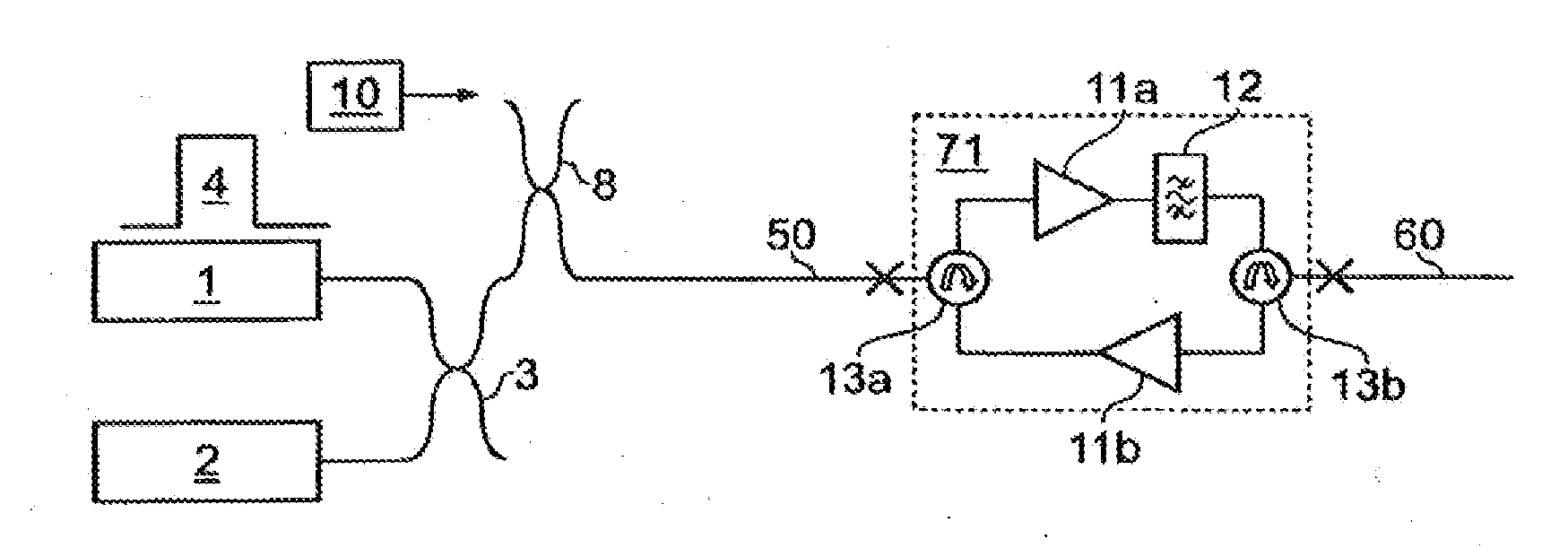
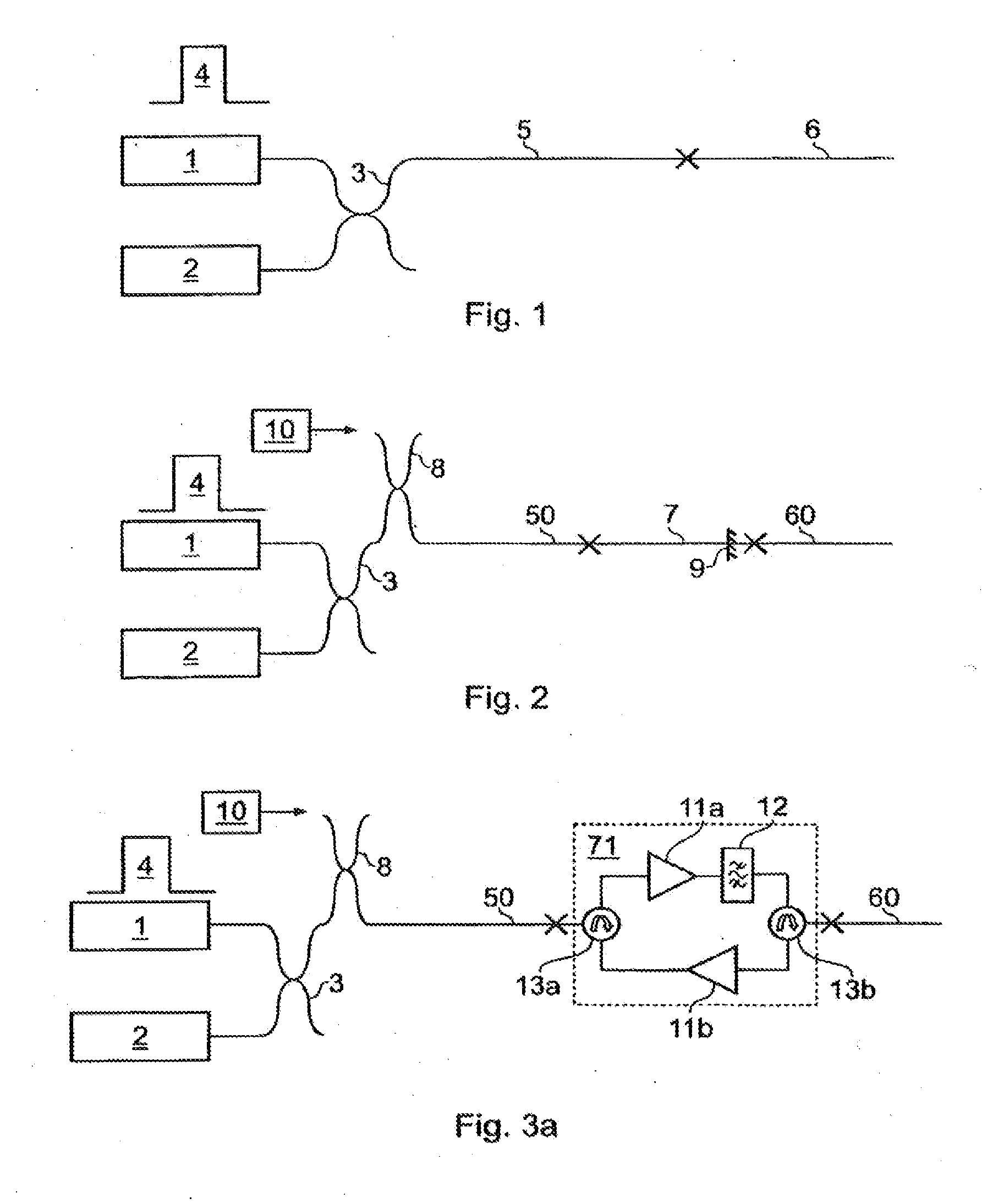
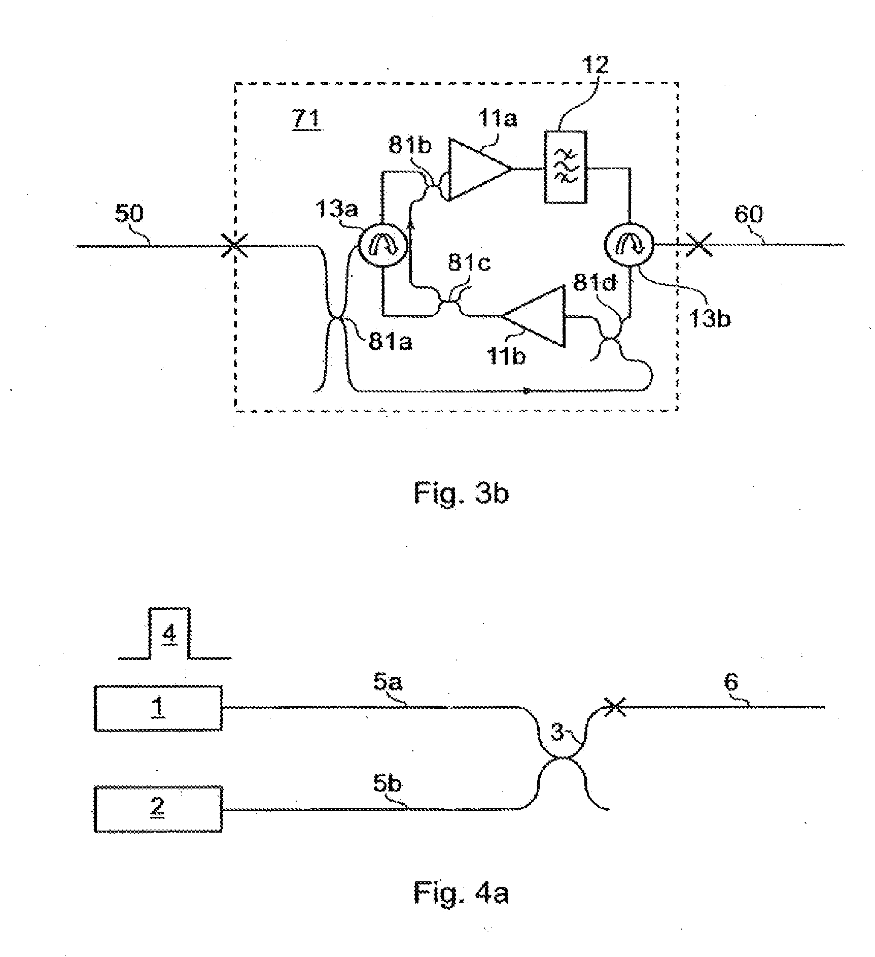
[0027] According to an embodiment of a first aspect of the invention, a method can be provided in which the backscatter power from the remote end of an optical fiber can be increased, whilst allowing the power launched into the fiber to remain below non-linear limits. In this method, the optical fiber is made up of at least two sections of fiber, such that the numerical aperture increases monotonically with increasing distance from the instrumentation. This method is illustrated in FIG. 1, where an OTDR backscatter measuring apparatus, represented schematically by a source 1, detector 2 and coupler 3, launches high power pulses 4 into a first fiber 5. The intensity of pulses 4 is selected to be below the threshold for the non-linear effects of relevance (depending on the application of the system and its design, the limiting effects could be SRS, SBS, SPM or others). The section of primary interest is a second fiber 6 which is connected to fiber 5 at a distance Lf. Fiber 5 is select...


PUM

PropertyMeasurementUnit
temperatureaaaaaaaaaa
water depthaaaaaaaaaa

Abstract

An optical time domain reflectometry apparatus for sensing a parameter in a region of interest is characterized in that the optical fiber includes a first section into which optical radiation at the probe wavelength is launched and a second section deployed in the region of interest. The first section has a higher intensity threshold for the onset of non-linear effects than the second section. The source launches the optical radiation into the first section at an intensity lower than the non-linear effects intensity threshold of the first section but higher than the non-linear effects intensity threshold of the second section. The attenuation characteristics of the first section are chosen such that the intensity of the optical radiation at the probe wavelength that reaches the second section is below the threshold for the onset of non-linear effects of the second section.

Description

RELATED APPLICATIONS [0001] This application is a division of U.S. application Ser. No. 10 / 502,616, filed Jul. 26, 2004, which is a national stage filing of PCT International Application Number PCT / GB03 / 00385 filed on Jan. 30, 2003, which claims priority to Great Britain Application No. 0202159.0, filed Jan. 30, 2002. All of these patent applications are incorporated by reference herein in their entireties.FIELD OF THE INVENTION [0002] The present invention relates to optical fiber sensors based on optical time-domain reflectometry (OTDR) in which a pulse or series of pulses is launched into the fiber and the signal is returned to the launching end and originates in reflected or scattered light in the fiber. BACKGROUND [0003] One example of such sensors is the Raman OTDR sensor from which temperature profiles can be determined from the intensity distribution of the backscatter signal measured as a function of time from launching the probe pulse, or equivalently, distance along the f...

Claims


Application Information

Patent Timeline
Patent Type & Authority Applications(United States)
IPC IPC(8): G01N21/47G01M11/00H04B10/071
CPCG01M11/3109H04B10/071G01M11/319G01K11/32
Inventor HARTOG, ARTHUR H.WAIT, PETER C.
Owner SCHLUMBERGER TECH CORP
Why Eureka
Try Eureka