Wireless Transmission Device, Wireless Reception Device, And Symbol Arranging Method

a wireless reception device and wireless transmission technology, applied in multiple modulation transmitter/receiver arrangements, orthogonal multiplex, multiplex communication, etc., can solve problems such as unrecognised and reception performance degradation, and achieve the effect of improving error rate performance and maintaining interference resistan

Active Publication Date: 2008-02-07
OPTIS WIRELESS TECH LLC
View PDF12 Cites 33 Cited by
  • Summary
  • Abstract
  • Description
  • Claims
  • Application Information

AI Technical Summary

Benefits of technology

The present invention helps to reduce interference and improve the accuracy of a receiver by using frequency diversity and time diversity effects.

Problems solved by technology

The patent text discusses the problem of high-speed and large capacity wireless data communication in mobile communication using radio waves. This is because the influence of wave delays due to multipath cannot be ignored, and the reception performance deterioration may caused due to frequency selective fading. The text focuses on the use of OFDM (Orthogonal Frequency Division Multiplexing) schemes, specifically the combination of CDMA (Code Division Multiple Access) and the MC-CDMA schemes (also known as the OFCDM scheme). The text describes the mapping of spreaded symbol in a frequency domain and a time domain, and the impact of wave delays and frequency selective fading on the transmission performance. The technical problem addressed by the patent is how to improve the reception performance and mitigate the impact of wave delays and frequency selective fading in high-speed and large capacity wireless data communication.

Method used


Image

  • Wireless Transmission Device, Wireless Reception Device, And Symbol Arranging Method
  • Wireless Transmission Device, Wireless Reception Device, And Symbol Arranging Method
  • Wireless Transmission Device, Wireless Reception Device, And Symbol Arranging Method

Examples


embodiment 1

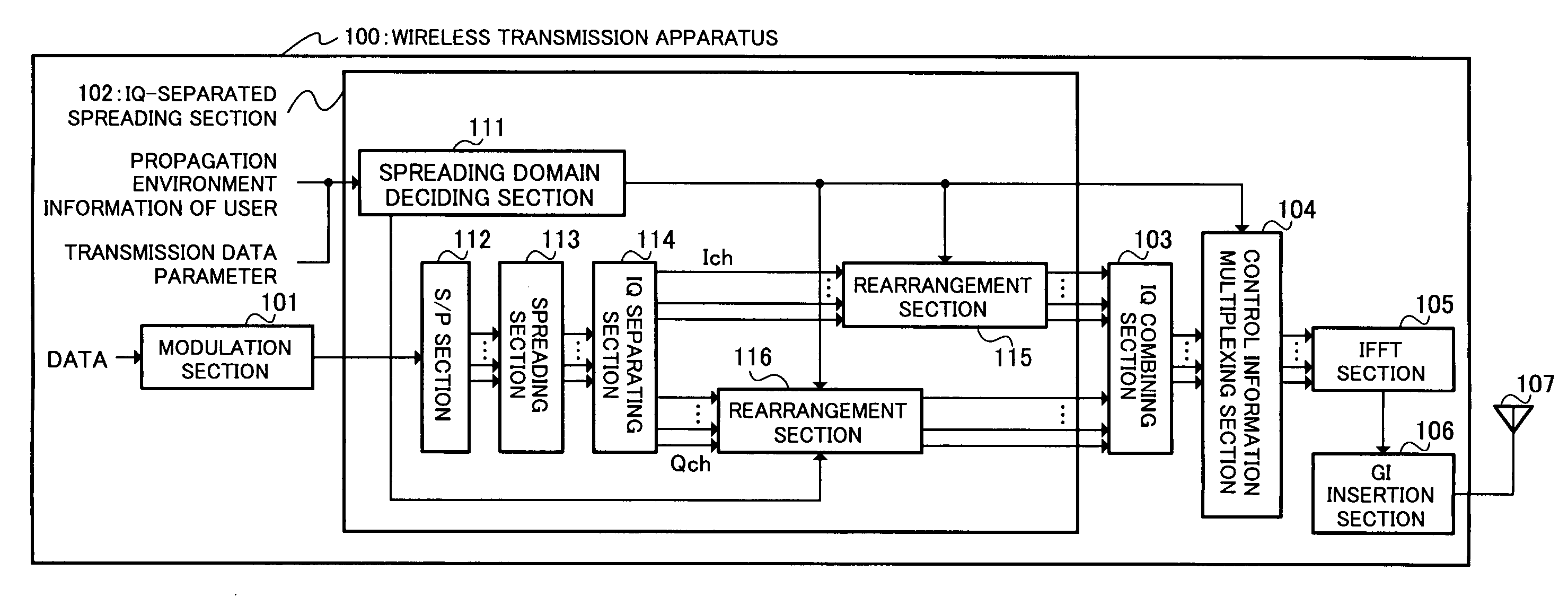
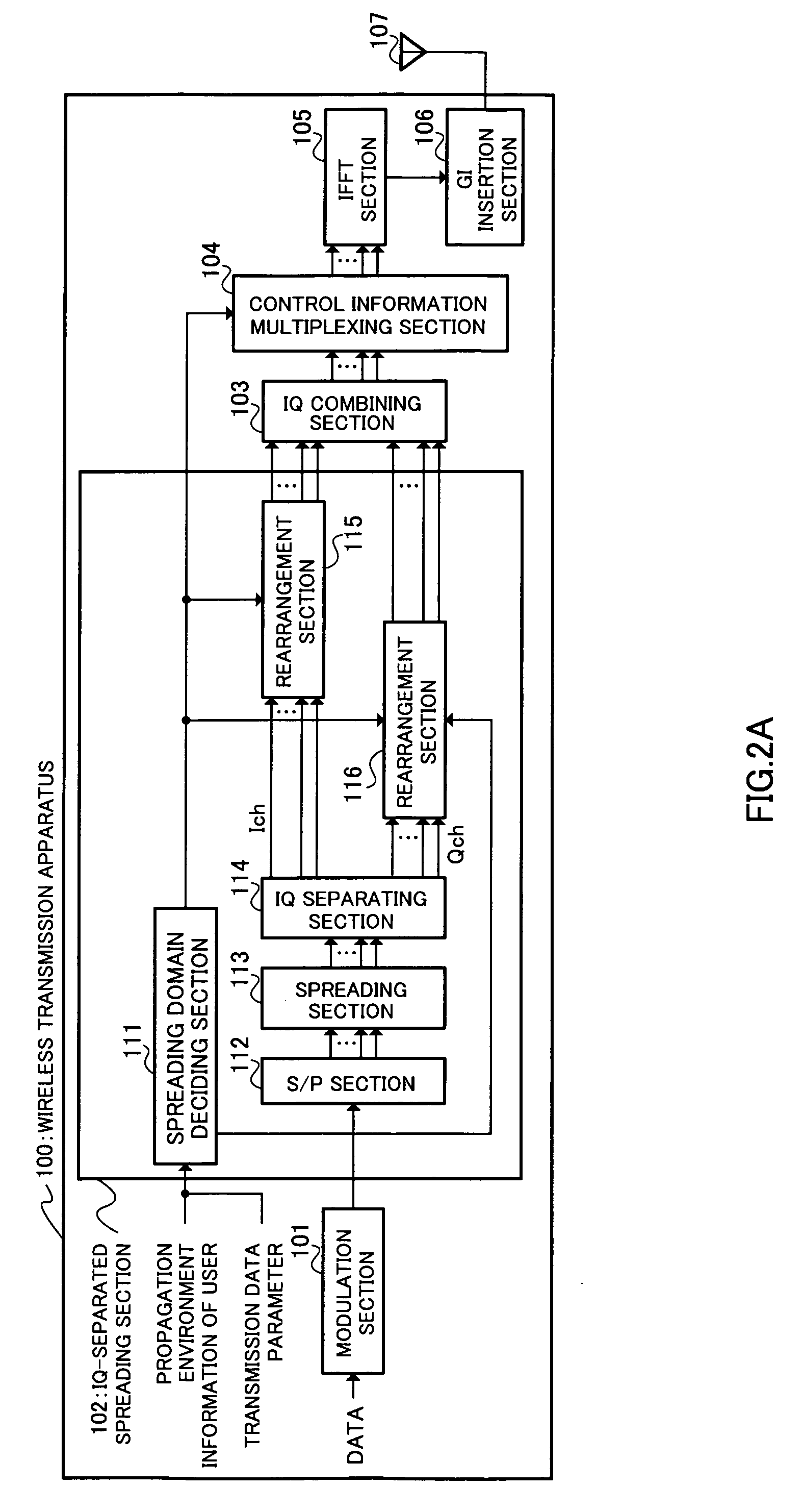
[0038]FIG. 1A and FIG. 2B are block views respectively showing a wireless transmission apparatus and wireless receiving apparatus of the MC-CDMA scheme of Embodiment 1 of the present invention. A wireless transmission apparatus is used as a base station apparatus in a mobile communication system. Further, a wireless receiving apparatus is used as a mobile terminal apparatus in a mobile communication system. Namely, the wireless transmission apparatus and wireless receiving apparatus are utilized in downlink data transmission. The wireless transmission apparatus and the wireless receiving apparatus can be used for uplink data transmission as a mobile terminal apparatus and base station apparatus, respectively.

[0039] Wireless transmission apparatus 100 shown in FIG. 2A has: modulation section 101 that modulates data for a user (wireless receiving apparatus 150) and generates modulation symbols comprised of an in-phase component (Ich component) and quadrature component (Qch component)...

embodiment 2

[0092]FIG. 14A and FIG. 14B are block views showing a wireless transmission apparatus and wireless receiving apparatus of Embodiment 2 of the present invention, respectively. Apparatuses described in this embodiment have a basic configuration the same as that described in Embodiment 1, and components that are the same are assigned the same reference codes, and their detailed descriptions will be omitted.

[0093] Wireless transmission apparatus 200 shown in FIG. 14A has a configuration where IQ-separated spreading section 201 is provided in place of IQ-separated spreading section 102 described in Embodiment 1. IQ-separated spreading section 201 has S / P section 112, rearrangement sections 115 and 116 described in Embodiment 1, and, in addition, has spreading domain and method deciding section 211, spreading code generating sections 212 and 213, IQ separating section 214, and spreading sections 215 and 216.

[0094] At IQ-separated spreading section 201 of wireless transmission apparatus ...

embodiment 3

[0107]FIG. 16A and FIG. 16B are block views showing a wireless transmission apparatus and wireless receiving apparatus of Embodiment 3 of the present invention. Apparatuses described in this embodiment have a basic configuration the same as that described in Embodiment 2, and components that are the same are assigned the same reference codes, and their detailed descriptions will be omitted.

[0108] Wireless transmission apparatus 300 shown in FIG. 16A has a configuration where IQ-separated spreading section 301 is provided in place of IQ-separated spreading section 201 described in Embodiment 2. IQ-separated spreading section 301 has a configuration where spreading domain assignment section 302 is added to IQ-separated spreading section 201, and spreading domain and method deciding section 303 is provided in place of spreading domain and method deciding section 211. Further, wireless receiving apparatus 350 shown in FIG. 16B has a configuration where IQ-separated despreading section ...


PUM


Abstract

A wireless transmission device enabled to improve an error rate performance at a receiver, by acquiring at least one of frequency diversity effect and a time diversity effect while keeping the interference resistance which is acquired by diffusion. In this transmission device, a modulation unit (101) modulates data to create a modulation symbol having in-phase components and quadrature components. An IQ individual spreading unit (102) arranges the diffusion chips, which are obtained by spreading the modulation symbol, of the in-phase components and the quadrature components, in areas extending in diffusion domains set individually for the in-phase components and the quadrature components. An IQ combining unit (103) combines the arranged spreading chips of the in-phase components and the quadrature components.

Description


Claims


Application Information

Patent Timeline
Owner OPTIS WIRELESS TECH LLC
Why Eureka
Try Eureka