Communication relay apparatus and communication relay method

a relay and relay technology, applied in repeater circuits, frequency-division multiplexes, high-level techniques, etc., can solve the problems of significant attenuation due to transmission distance, short radio frequency resources, etc., to prevent the overall data throughput of the communication system from decreasing, improve error rate performance, and improve throughput

Active Publication Date: 2009-04-09
APPLE INC
View PDF5 Cites 108 Cited by
  • Summary
  • Abstract
  • Description
  • Claims
  • Application Information

AI Technical Summary

Benefits of technology

[0011]According to the present invention, when communication is relayed among a plurality of communication terminals, it is possible to improve throughput by improving error rate performance at the receiving station and prevent the overall data throughput of the communication system from decreasing by reducing interference power.

Problems solved by technology

However, radio frequencies which are finite resources are running short, and it is actively studied to utilize high frequency bands and realize a high transmission rate in order to realize high-capacity data transmission.
When high frequency radio bands are utilized, a high transmission rate can be expected in a short distance, but attenuation due to a transmission distance is significant.

Method used


Image

  • Communication relay apparatus and communication relay method
  • Communication relay apparatus and communication relay method
  • Communication relay apparatus and communication relay method

Examples


embodiment 1

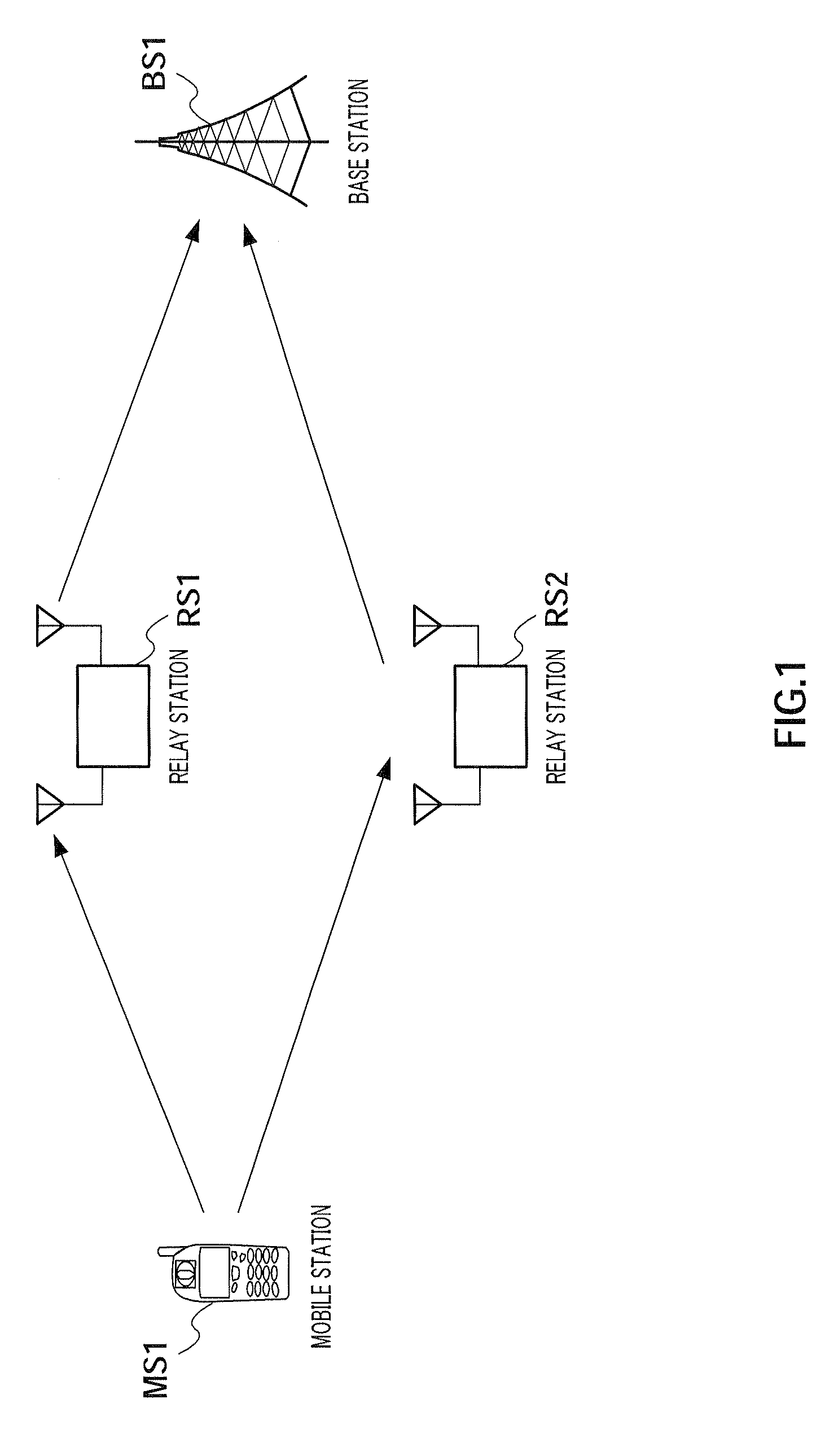
[0036]FIG. 1 shows an outline of the communication system according to Embodiment 1 of the present invention.

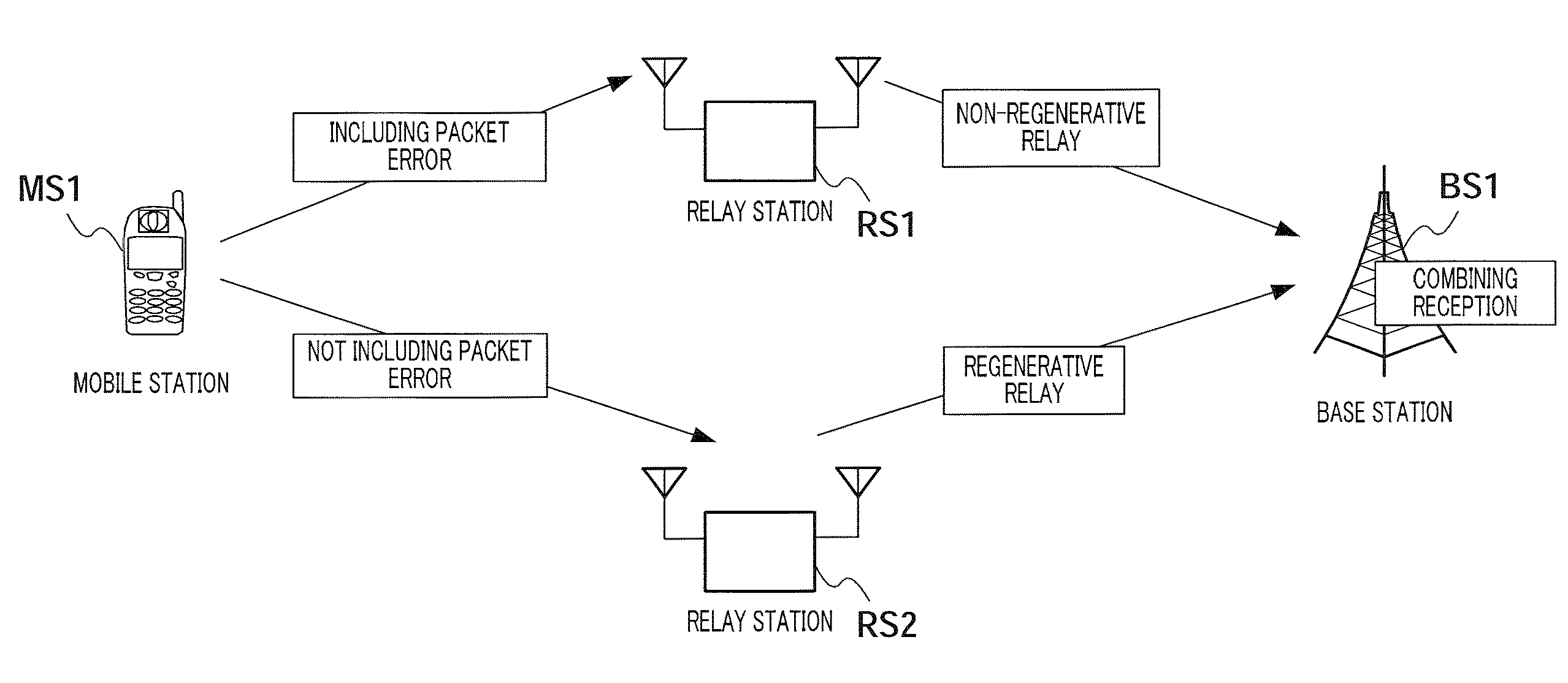
[0037]This communication system includes mobile station MS1, relay stations RS1 and RS2, and base station BS1, and mobile station MS1 is located outside the cellular service area managed by base station BS1. The user of mobile station MS1 desires to communicate with base station BS1. However, mobile station MS1 is located outside the cellular service area, and therefore is unable to perform communication in this situation. Therefore, in the communication system according to this embodiment, relay station RS1 or relay station RS2 located between mobile station MS1 and base station BS1 is made to relay communication between mobile station MS1 and base station BS1. In addition, for ease of explanation, a case will be described as an example where signals are transmitted from mobile station MS1 to base station BS1, that is, uplink communication (uplink relay).

[0038]In the communi...

embodiment 2

[0100]The communication relay apparatus according to Embodiment 2 of the present invention compares a subcarrier determined to have good received quality in relay determination with a hard decision threshold value. Then, the received symbol of a subcarrier having better received quality than the hard decision threshold value is subjected to a hard decision and re-modulation, and transferred.

[0101]The basic configuration of the communication relay apparatus according to this embodiment is the same as communication relay apparatus 100 described in Embodiment 1. Therefore, the same parts will not be described, and non-regenerative relay processing section 210 which is a different configuration from communication relay apparatus 100 will be described below.

[0102]FIG. 14 is a block diagram showing the main internal configuration of non-regenerative relay processing section 210. The components that are the same as non-regenerative relay processing section 110 (refer to FIG. 4) described i...

embodiment 3

[0124]In Embodiment 3 of the present invention, in a non-regenerative relay, the amplification factor of transmission power for subcarriers having poor received quality is set relatively higher than an amplification factor of transmission power for subcarriers having good received quality. By this means, it is possible to reduce the influence of interference against base station BS1, which is the receiving station.

[0125]The basic configuration of the communication relay apparatus according to this embodiment is the same as communication relay apparatus 100 described in Embodiment 1. Therefore, explanation of the same parts will be omitted, and the configuration of non-regenerative relay processing section 110 and its surroundings which is different from communication relay apparatus 100 will be described below.

[0126]FIG. 20 is a block diagram showing the configuration of non-regenerative relay processing section 110 and its surroundings.

[0127]Weight coefficient calculating section 3...


PUM


Abstract

A communication relay apparatus wherein the error rate characteristic of a relay destination is improved to raise the throughput, while reducing the given interference power to prevent the reduction of the throughput of the whole communication system. In the apparatus, a signal addressed to a base station is received (ST1010), and a decoding process and other processes are performed (ST1020). A bit error determination is performed (ST1030), and if there is no bit error, a reproduction/relay process (ST1050) is performed. If there is any bit error, a threshold-based determination of reception quality is performed for each of subcarriers (ST1120-1130). If the reception quality is greater than a threshold value, the corresponding subcarrier is outputted (ST1140); otherwise, the corresponding subcarrier is not relayed (ST1150). A signal, which has been subjected to either process, is transmitted (ST1060).

Description

TECHNICAL FIELD[0001]The present invention relates to a communication relay apparatus and communication relay method.BACKGROUND ART[0002]In recent years, with spread of broadband communication services at home, also in a mobile communication system of a cellular scheme, research and development are actively conducted for the purpose of providing high-capacity data communication services. However, radio frequencies which are finite resources are running short, and it is actively studied to utilize high frequency bands and realize a high transmission rate in order to realize high-capacity data transmission.[0003]When high frequency radio bands are utilized, a high transmission rate can be expected in a short distance, but attenuation due to a transmission distance is significant. Therefore, when high frequency radio bands are utilized in a real system, for example, the coverage area of a base station becomes small, and it is necessary to provide more base stations. Providing base stat...

Claims


Application Information

Patent Timeline
Patent Type & Authority Applications(United States)
IPC IPC(8): H04B7/15
CPCH04B7/15542H04W28/18H04W16/26Y02D30/70
Inventor IMAMURA, DAICHIHORIUCHI, AYAKOMIYOSHI, KENICHI
Owner APPLE INC
Why Eureka
Try Eureka