

Slide fastener slider
- Summary
- Abstract
- Description
- Claims
- Application Information
AI Technical Summary
Benefits of technology
Problems solved by technology
Method used
Image

Examples
first embodiment
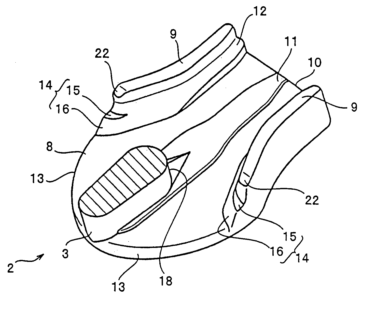
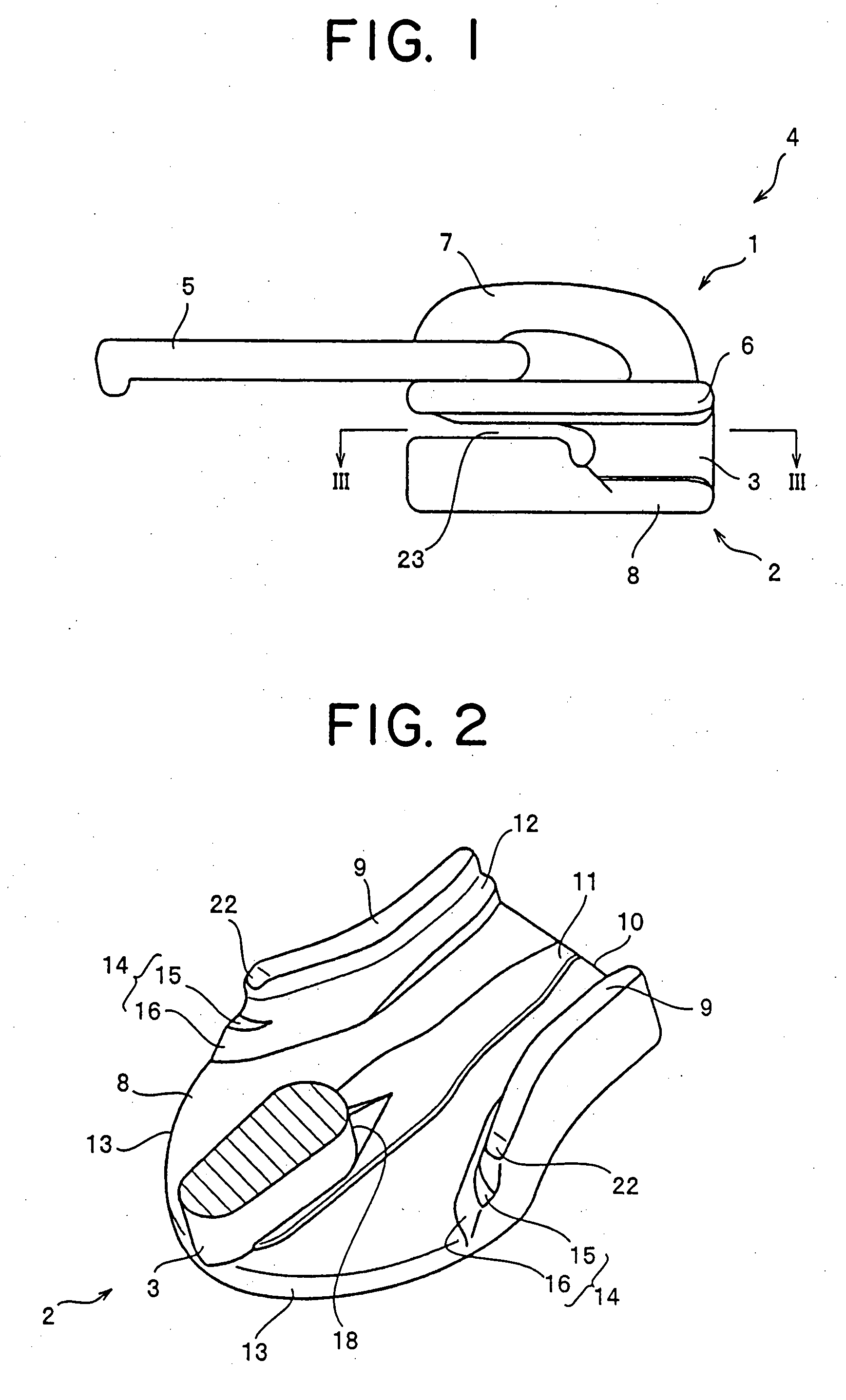
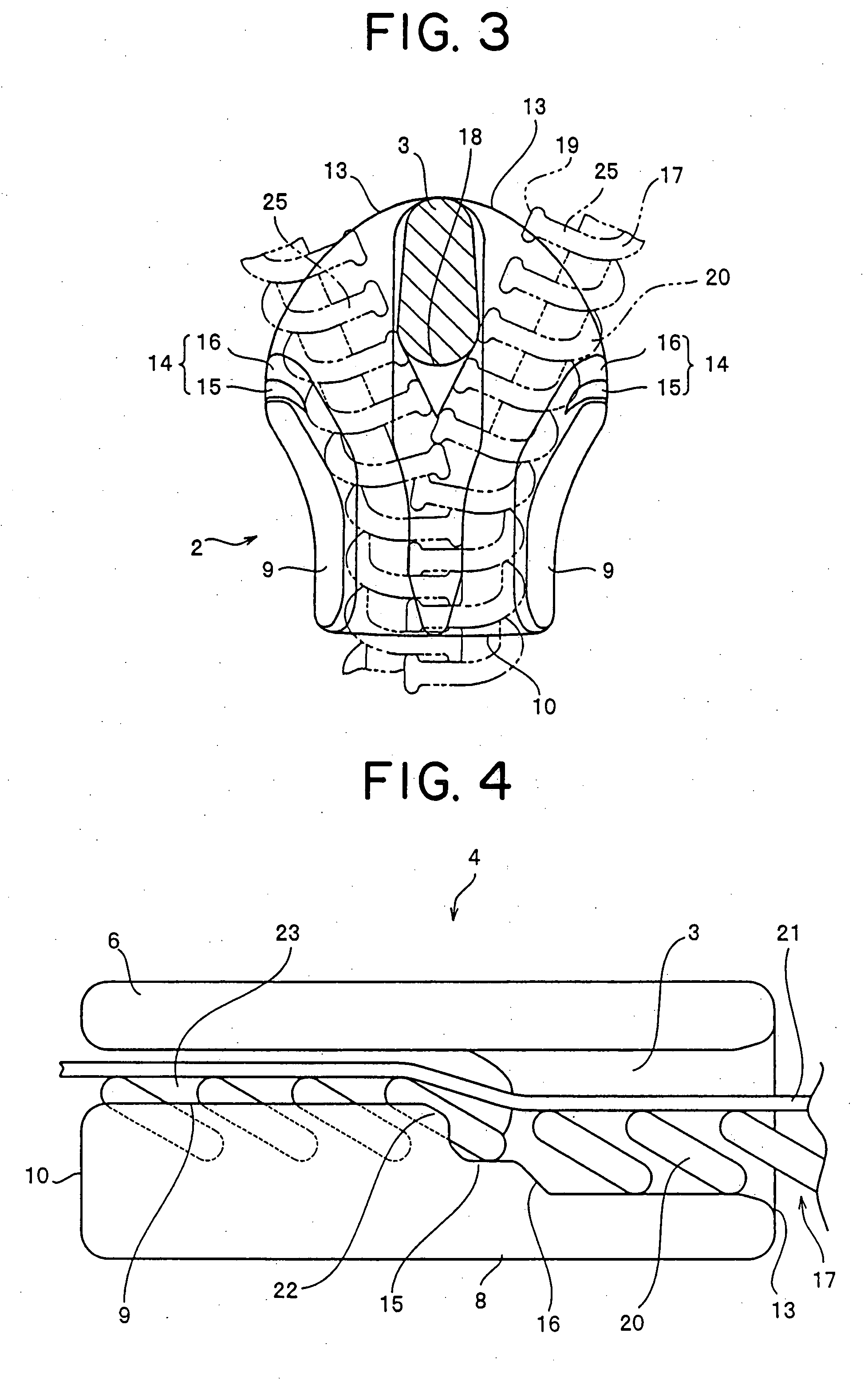
[0048]FIG. 1 is a side view of a slide fastener slider according to an embodiment of the present invention. FIG. 2 is an entire perspective view of a lower blade of the slide fastener slider of the invention when viewed from above. FIG. 3 is a sectional view taken along the line III-III in FIG. 1. FIG. 4 is a partial sectional view of the slide fastener slider of the invention. FIG. 5 is a sectional view of major portions of the slide fastener slider before the posture of an element is displaced. FIG. 6 is a sectional view of major portions of the slide fastener slider after the posture of the element is displaced.
[0049]As shown in FIG. 1, in the slide fastener slider, an upper blade 1 and a lower blade 2 are connected and fixed integrally with a connecting post so as to configure a slider body 4. A pull tag 5 is provided on the upper blade 1. An element passage 23 is formed inside the slider body 4 such that linear elements 17 can be inserted.
[0050]The upper blade 1 is constituted ...
PUM
 Abstract
Description
Claims
Application Information