Fan control apparatus

Active Publication Date: 2009-04-30
TOYOTA JIDOSHA KK
View PDF7 Cites 1 Cited by
  • Summary
  • Abstract
  • Description
  • Claims
  • Application Information

AI Technical Summary

Benefits of technology

[0016]Because the fluid supply unit is of an air bleed type in which the air is supplied to the fan, surge, or the like, can easily occur and the engine can be easily overloaded. Therefore, with the above-described configuration, the present inventio

Problems solved by technology

However, immediately after one engine fails, the revolution speed of the normally operating engine is low.
As a result, when the required output abruptly incre

Method used


Image

  • Fan control apparatus
  • Fan control apparatus
  • Fan control apparatus

Examples


Example

[0022]A propulsion fan control apparatus of an embodiment of the present invention will be described below with reference to the appended drawings.

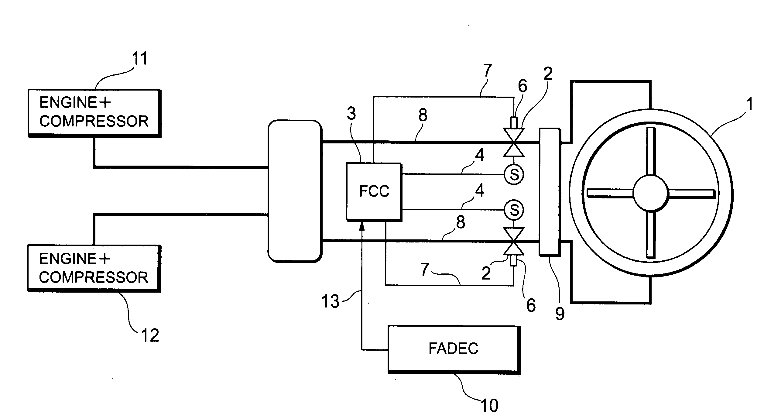
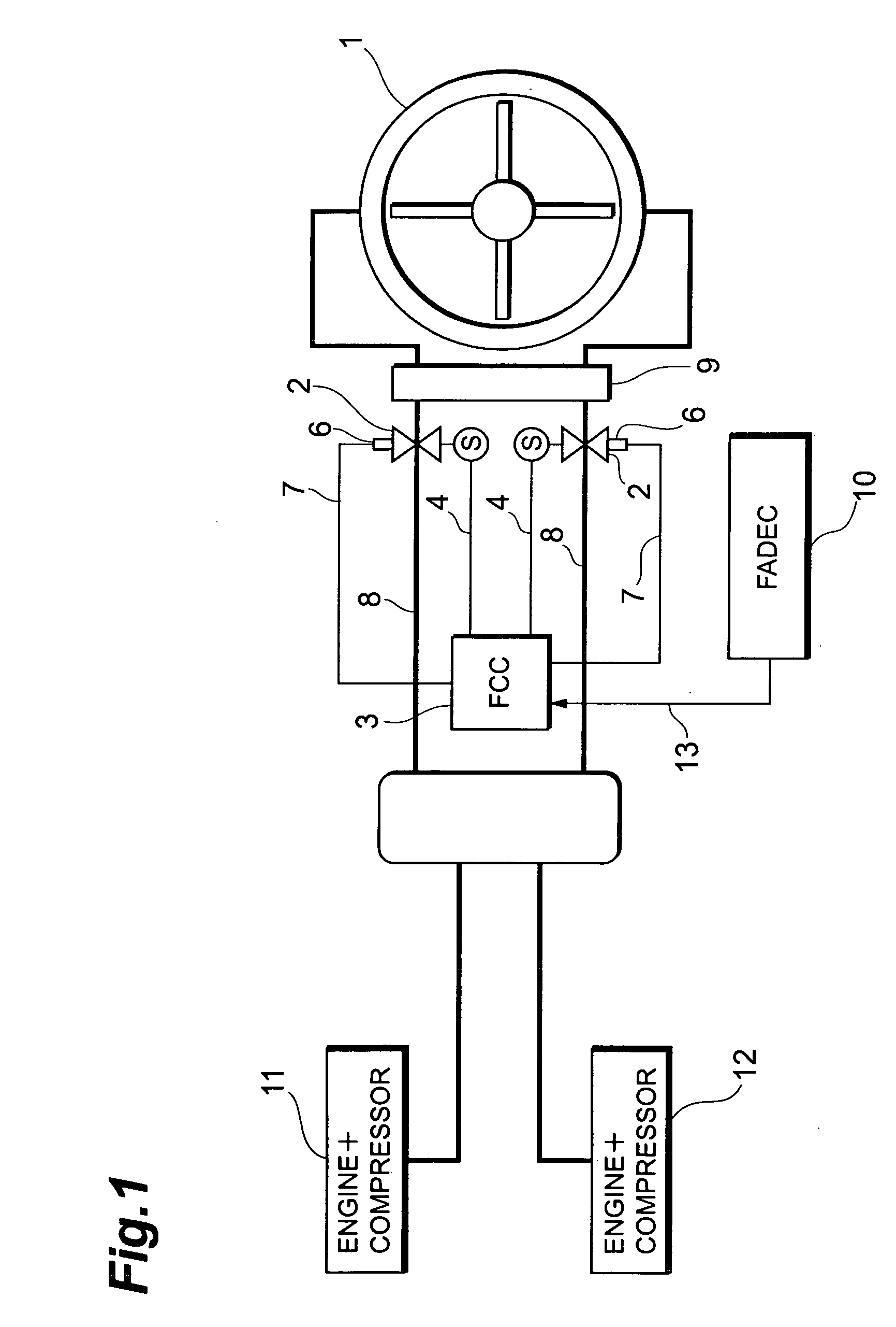
[0023]FIG. 1 illustrates the configuration of a propulsion fan control apparatus of an embodiment. As shown in FIG. 1, the propulsion fan control apparatus of the present embodiment serves to control the operation of a fan that generates a propulsion force of a VTOL apparatus and comprises a fan 1, flow rate control valves 2, an FCC 3, opening degree sensors 6, air supply systems 8, a collector pipe 9, an FADEC 10, and engine+compressor combinations 11, 12.

[0024]The engine+compressor combinations 11, 12 serve to supply the compressed air as a drive source to the fan 1 and are composed of an air source bleed gas turbine engine and a compressor. A reciprocal engine, a rotary engine, or an electric motor also can be employed as a power source for driving the compressor. The engine+compressor combinations 11, 12 function as fluid supply units...


PUM


Abstract

When a FADEC detects an abnormality in any of engine+compressor combinations, a FCC controls the amount of air for driving the fan to a level that is lower than that before the abnormality has been detected, until a state is assumed in which the normally operating engine+compressor combination can supply the air at a flow rate necessary for a fan to generate a propulsion force that has been attained before the abnormality has been detected. As a result, the normally operating engine+compressor combination can be prevented from the occurrence of a surge and a resultant overload state. Therefore, when some drive sources from a plurality of drive sources fail, normally operating drive sources can be prevented from being in an overload state.

Description

BACKGROUND OF THE INVENTION[0001]1. Field of the Invention[0002]The present invention relates to a fan control apparatus, and more particularly to a fan control apparatus that controls a fan that is rotary driven by being supplied with a fluid and serves to generate a propulsion force of a flying object.[0003]2. Description of the Related Art[0004]A propulsion force for causing a VTOL (Vertical Take-off and Landing) apparatus to fly has conventionally been obtained by supplying the air by an bleed gas turbine engine and rotary driving a fan. For example, Japanese Patent Application Laid-open No. 2005-125976 discloses a VTOL apparatus having a transfer system of a high-pressure gas type. With such configuration, a drive source takes in the air from an air suction port and compresses the air with a compressor. The compressed high-pressure gas is transferred through a pipe and blown onto an input shaft of the fan to rotate the fan. Based on the fail-safe approach, two drive sources of ...

Claims


Application Information

Patent Timeline
IPC IPC(8): F02K3/04
CPCF02C6/206F02C9/20F05D2270/093F05D2220/329F05D2270/09F02K3/04
Inventor ISHIBA, MASATSUGU
Owner TOYOTA JIDOSHA KK
Why Eureka
Try Eureka