Illuminated flying kite

a kite and kite technology, applied in the field of flying devices, can solve the problems of limiting the time of flying a kite in low light conditions or at night, and virtually impossible to fly a kite in visible light hours

Inactive Publication Date: 2008-02-14
HASSETT DONALD W +1
View PDF4 Cites 9 Cited by
  • Summary
  • Abstract
  • Description
  • Claims
  • Application Information

AI Technical Summary

Benefits of technology

[0007]It is the object of the present invention to provide a flying kite that has

Problems solved by technology

One problem with kite flying is that it is restricted to visible light hour

Method used


Image

  • Illuminated flying kite
  • Illuminated flying kite
  • Illuminated flying kite

Examples


Embodiment Construction

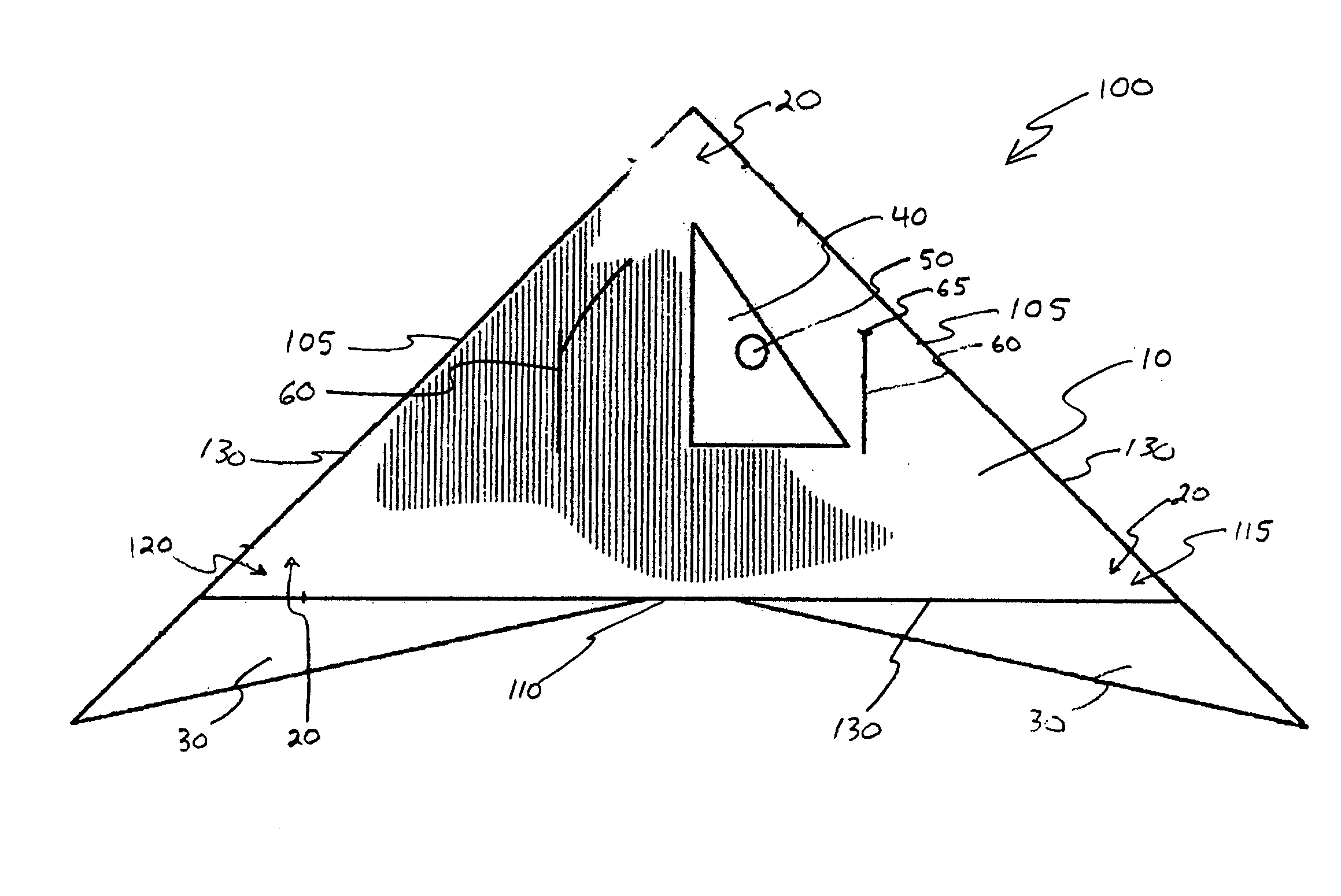
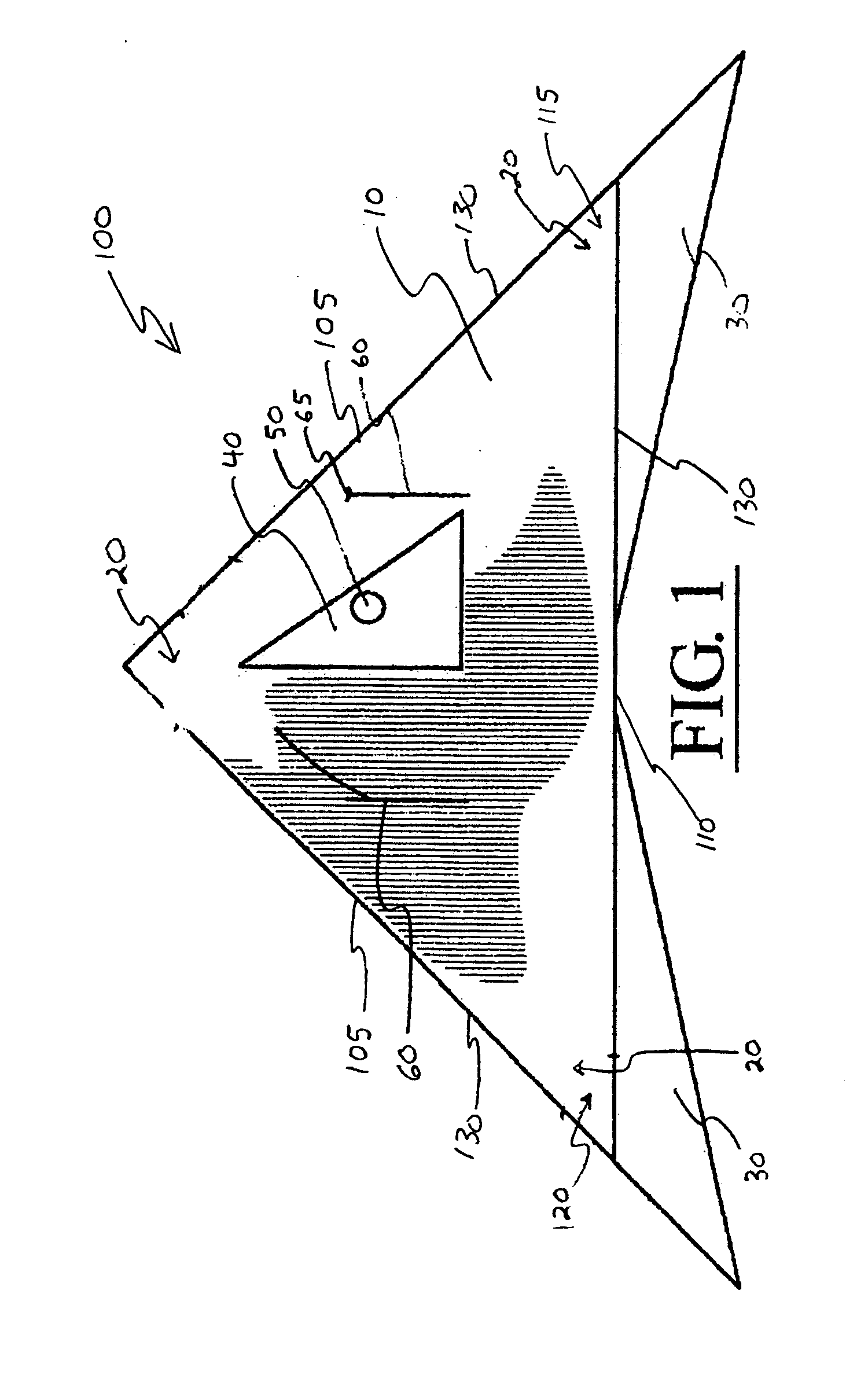
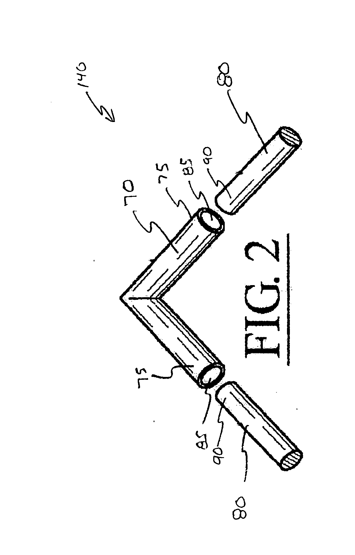
[0016]Referring now to the embodiments in FIG. 1 through 3, and wherein the various elements depicted therein are not necessarily drawn to scale and wherein like elements are identified with like reference numerals, there is illustrated the components of a preferred embodiment of a flying kite 100 constructed according to the principles of the present invention.

[0017]The flying kite 100 is comprised of a body 10 that is configured in a substantially planar manner. The body 10 is manufactured from a durable lightweight material such as but not limited to cloth or plastic. It is further contemplated within the scope of the present invention that the body 10 be manufactured from a transparent or translucent material. As shown in FIG. 1 submitted herewith, the body 10 is generally triangular in shape. Those skilled in the art will recognize that the body 10 could be numerous different shapes in addition to and / or in conjunction with the shape as shown in the embodiment in FIG. 1. More s...


PUM


Abstract

A flying kite designed to be visible when flown in low light conditions. The flying kite includes a body that is generally triangular in shape and configured in a substantially planar manner. The flying kite also comprises a frame that provides structural support for the body. The frame includes three corner frame members and three longitudinal frame members that are interposed the corner frame members. The longitudinal frame members further include two compartments having disposed therein the chemicals necessary to create chemical luminescence subsequent to distressing the frame members. The flying kite further includes two pockets for receiving therein a conventional glowstick.

Description

FIELD OF THE INVENTION[0001]The present invention relates to a flying device, more specifically to a flying kite that is designed to be visible in low light conditions by utilizing chemical luminescence.BACKGROUND[0002]In the history of flight, the exact date and origin of the kite is not know but it is believed that kites were first flown in China more than two thousand years ago. The earliest written account of kite flying is about 200 B.C. when the Chinese General Han Hsin of the Han dynasty flew a kite over the walls of a city he was attacking to measure how far his army would have to tunnel to reach past the defenses. Kite flying was eventually spread by traders from China to Korea, and across Asia to India. Each area adopting a distinctive style of kite and cultural purpose for flying them.[0003]Men like Benjamin Franklin and Alexander Wilson used their knowledge of kite flying to learn more about the wind and the weather. Many early aviators such as the Wright Brothers experi...

Claims


Application Information

Patent Timeline
IPC IPC(8): B64C31/06
CPCA63H27/08
Inventor HASSETT, DONALD W.HASSETT, ALLISON
Owner HASSETT DONALD W
Why Eureka
Try Eureka