Placement angle error calibration method

A technology of angle error and angle correction, which is applied in the field of placement angle error correction, can solve the problems of time synchronization error, non-coincidence, and no correction method for placement angle error, such as airborne laser radar system

Inactive Publication Date: 2018-01-23
河南省科学院地理研究所 +1
View PDF0 Cites 7 Cited by
  • Summary
  • Abstract
  • Description
  • Claims
  • Application Information

AI Technical Summary

Problems solved by technology

[0005] The calibration of the airborne lidar system includes the calibration of each component and the calibration after system integration. Among them, even if every component that makes up the airborne lidar system has been calibrated and meets the accuracy requirements, in After the whole system is integrated, new errors will be generated after the components (sensors) are integrated into the system, mainly including eccentricity error, installation angle error, coordinate conversion error, time synchronization error, etc. Among them, the laser scanning reference coordinate system and the IMU The installation angle error between the inertial measurement units is the largest source of system error. The installation angle error will cause the point clouds of the buildings in the two adjacent airways to not overlap. If the installation angle error correction is not performed, the point cloud After classification and extraction, the installation angle error will be introduced into the final point cloud data. Therefore, for the airborne lidar measurement system, satisfactory measurement accuracy cannot be obtained without calibration after system integration
[0006] At present, there is no effective correction method for positioning angle error to improve the accuracy of airborne lidar system

Method used


Image

  • Placement angle error calibration method
  • Placement angle error calibration method
  • Placement angle error calibration method

Examples


Embodiment Construction

[0061] Embodiments of the present invention will be described in detail below in conjunction with the accompanying drawings.

[0062] It should be clear that the described embodiments are only some of the embodiments of the present invention, not all of them. Based on the embodiments of the present invention, all other embodiments obtained by persons of ordinary skill in the art without creative efforts fall within the protection scope of the present invention.

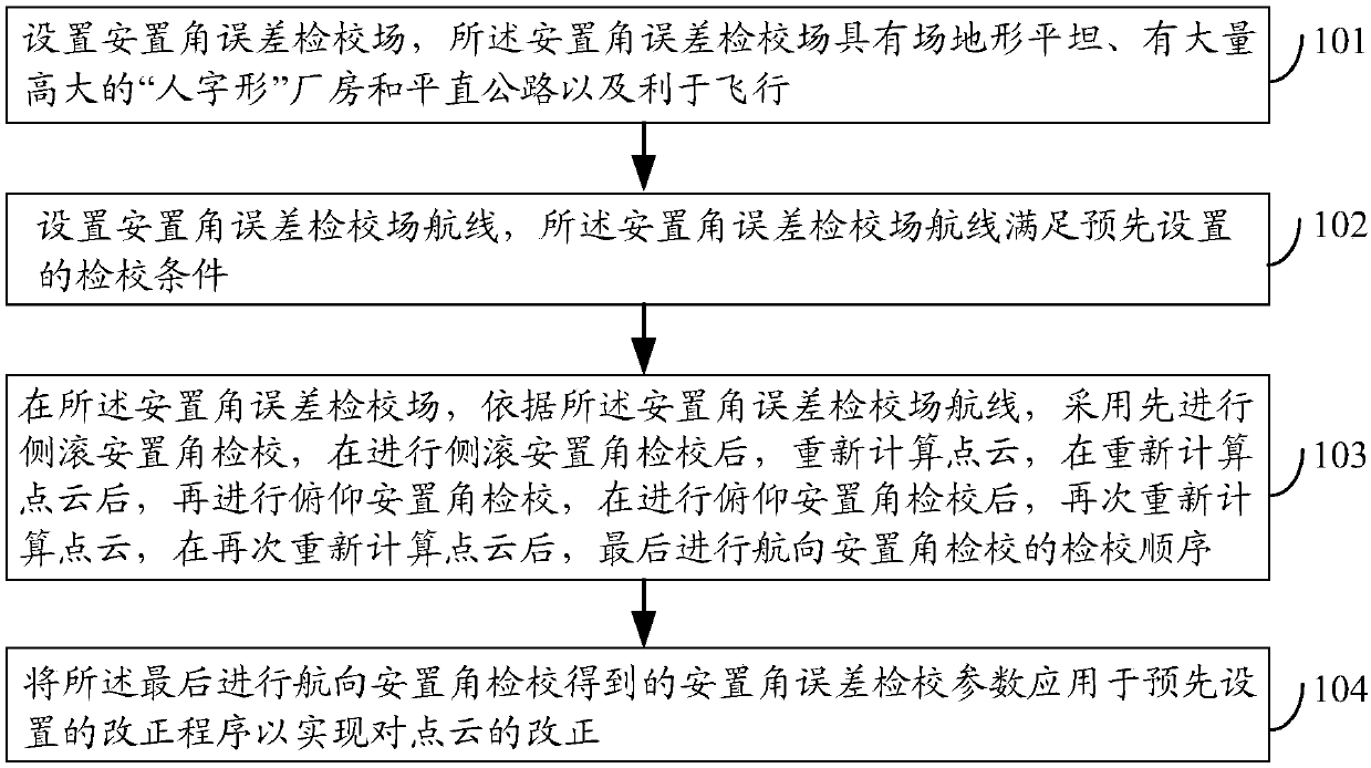
[0063] figure 1 It is a schematic flow chart of an installation angle error checking method in an embodiment of the present invention, as figure 1 As shown, the method of this embodiment may include:

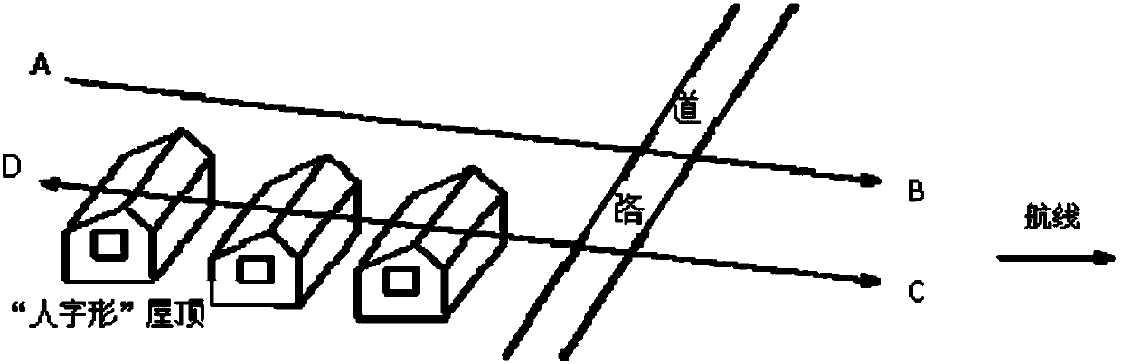
[0064] Step 101, setting up an installation angle error calibration field, which has a flat terrain, a large number of tall "herringbone" factory buildings and straight roads, and is conducive to flying;

[0065] In this embodiment, as an optional embodiment, the installation angle error calibration field is selected...


PUM


Abstract

An embodiment of the invention discloses a placement angle error calibration method and relates to the calibration technology. The method can improve precision of an airborne laser radar system. The method comprises the following steps: setting a placement angle error calibration field, wherein the placement angle error calibration field has flat terrain, has a lot of tall V-shaped factories and flat and straight roads and facilitates flying; setting a placement angle error calibration field air route meeting preset calibration conditions; in the placement angle error calibration field, according to the placement angle error calibration field air route, carrying out roll placement angle calibration first, and carrying out point cloud recalculation; then, carrying out pitch placement anglecalibration after point cloud recalculation; carrying out point cloud recalculation again after pitch placement angle calibration; finally, carrying out heading placement angle calibration after pointcloud recalculation; and applying placement angle error calibration parameters obtained through the final heading placement angle calibration to a preset correction program to realize correction of the point cloud. The method is suitable for placement angle error calibration.

Description

technical field [0001] The invention relates to a verification technology, in particular to a method for verifying an installation angle error. Background technique [0002] Due to its simple shape and light weight, the airborne lidar system can carry many flying platforms, and has an effective scanning field of view of 70° and a high scanning density of up to 200K pulses per second, which can effectively improve the scanning efficiency of aerial surveying and mapping, and can It is well adapted to the needs of mountainous landforms and efficient aerial survey operations in my country, and has been widely used, for example, 3D data acquisition of power line inspection, 3D urban information modeling, cadastral survey and monitoring, water conservancy survey, forest and vegetation inspection, etc. Various high-efficiency and high-precision three-dimensional measurement fields. [0003] The airborne laser scanning measuring instrument (three-dimensional imaging) in the airborne ...

Claims


Application Information

Patent Timeline
Patent Type & Authority Applications(China)
IPC IPC(8): G01S7/497
Inventor 李军杰王超王丽媛杨春邱士可张鹏飞杨保杜军马玉凤郝利民宋立生
Owner 河南省科学院地理研究所
Why Eureka
Try Eureka