Multi-rotor unmanned aerial vehicle

A multi-rotor unmanned aerial vehicle, rotor technology, applied in the field of unmanned aerial vehicles, can solve problems such as fuselage tilt

Active Publication Date: 2018-06-19
SHENYANG WOOZOOM TECH CO LTD
View PDF5 Cites 10 Cited by
  • Summary
  • Abstract
  • Description
  • Claims
  • Application Information

AI Technical Summary

Problems solved by technology

[0003] The purpose of this disclosure is to provide a multi-rotor drone to solve the problem of the tilt of the fuselage of the drone when it moves laterally

Method used


Image

  • Multi-rotor unmanned aerial vehicle
  • Multi-rotor unmanned aerial vehicle
  • Multi-rotor unmanned aerial vehicle

Examples


Embodiment Construction

[0028] Specific embodiments of the present disclosure will be described in detail below in conjunction with the accompanying drawings. It should be understood that the specific embodiments described here are only used to illustrate and explain the present disclosure, and are not intended to limit the present disclosure.

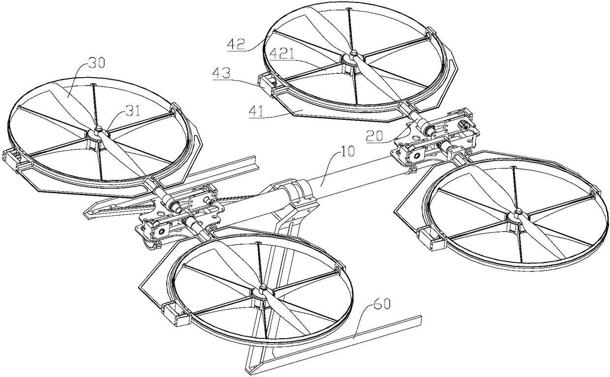
[0029] In this disclosure, unless stated to the contrary, the orientation words "up" and "down" used are defined based on the up and down directions of the UAV in the level flight state, and "inside" and "outside" are " refers to the outline of the corresponding parts, "horizontal" refers to the side direction of the UAV when it flies forward and backward, and "longitudinal" refers to the front and rear direction of the UAV. It should be noted that the front-to-back direction of UAV flight is defined according to its usage habits, the length extension direction of the fuselage is the front-to-back direction of UAV flight, and the horizontal direction is perpe...


PUM


Abstract

The invention discloses a multi-rotor unmanned aerial vehicle. The multi-rotor unmanned aerial vehicle comprises a vehicle body (10), supporting arms (20) extending outwards in the transverse direction from the vehicle body, rotors (30), first supporting frames (41) fixed to the end portions of the supporting arms and provided with hollow regions capable of containing the rotors, first tilting steering engines (43) fixed to the first supporting frames, and second supporting frames (42) located in the hollow regions and connected to output shafts of the first tilting steering engines, wherein the rotors are fixed to the second supporting frames through first motors (31) so as to be driven by the first tilting steering engines to transversely tilt. When the unmanned aerial vehicle moves transversely, the transversely-tilting rotors can supply lift force maintaining the unmanned aerial vehicle at a certain height and can supply transverse motion power to the unmanned aerial vehicle, and meanwhile the vehicle body does not incline. Due to the fact that the rotors are contained in the hollow regions formed by the first supporting frames, the rotors can tilt at large angles in the hollowregions, and only generation of the power in the horizontal direction and the lift force in the vertical direction needs to be guaranteed.

Description

technical field [0001] The present disclosure relates to the technical field of unmanned aerial vehicles, in particular, to a multi-rotor unmanned aerial vehicle. Background technique [0002] The multi-rotor drone realizes the change of the lift force of the drone by adjusting the speed of each rotor, thereby controlling the attitude and position of the drone. When the existing UAV changes its attitude and position, the flight control system adjusts the speed of the motor connected to the rotor. When the UAV moves in four directions in the horizontal plane, the flight control system must adjust the motor speed to make the machine The body is tilted at a certain angle. In this case, if other devices such as gimbal cameras and infrared devices are mounted, these devices also need to make corresponding tilt movements with the tilt of the fuselage in order to ensure stable monitoring of the mission target. . In addition, when the fuselage is tilted, the UAV is subject to grea...

Claims


Application Information

Patent Timeline
Patent Type & Authority Applications(China)
IPC IPC(8): B64C27/08B64C27/52
CPCB64C27/08B64C27/52B64U30/20B64U50/19B64U10/10
Inventor 宋大雷肖川梅森林天宇
Owner SHENYANG WOOZOOM TECH CO LTD
Why Eureka
Try Eureka