
Utility meter using temperature compensation

a technology of utility meters and compensation points, applied in the field of utility meters, can solve the problems of customer overbilling or underbilling, ambient temperature variations often affecting and the accuracy of utility meters is ambient temperatur

Inactive Publication Date: 2008-02-14
LANDIS GYR LLC
View PDF14 Cites 23 Cited by
  • Summary
  • Abstract
  • Description
  • Claims
  • Application Information

AI Technical Summary

Benefits of technology

"The present invention provides a sensor and circuitry that can detect temperature near a time keeping component and adjust the time keeping function accordingly. This compensates for variations in temperature that may affect the operation of the time keeping component. The invention can be used in utility meters to adjust the clock maintained by the time keeping function based on the detected temperature. This helps to ensure accurate timing signals even when the temperature changes."

Problems solved by technology

One factor affecting the accuracy of utility meters is ambient temperature.
In particular, ambient temperature variations often affect a meter's ability to measure time accurately.
Accordingly, time measurement errors may cause a meter to generate faulty customer usage information, thereby resulting in customer overbilling or underbilling.
For example, electrical energy may cost more during the afternoon in the summer months than at night during the winter months.
However, line power is not available during a power outage.
Crystal oscillators, however, are susceptible to operational variations based on ambient temperature variations.
Such operational variations can result in significant inaccuracies in time-keeping even during short duration power outages.
Moreover, for non-electricity meters that rely on crystal oscillators full-time, inaccuracies could be substantial.

Method used


Image

  • Utility meter using temperature compensation
  • Utility meter using temperature compensation
  • Utility meter using temperature compensation

Examples


Embodiment Construction

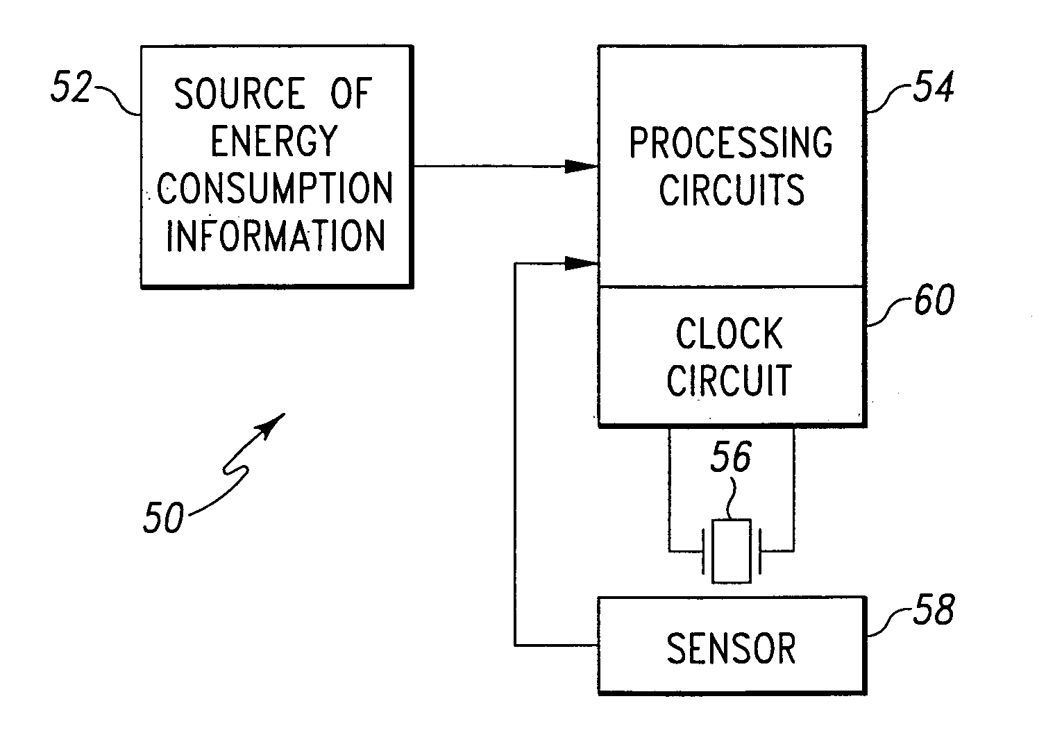
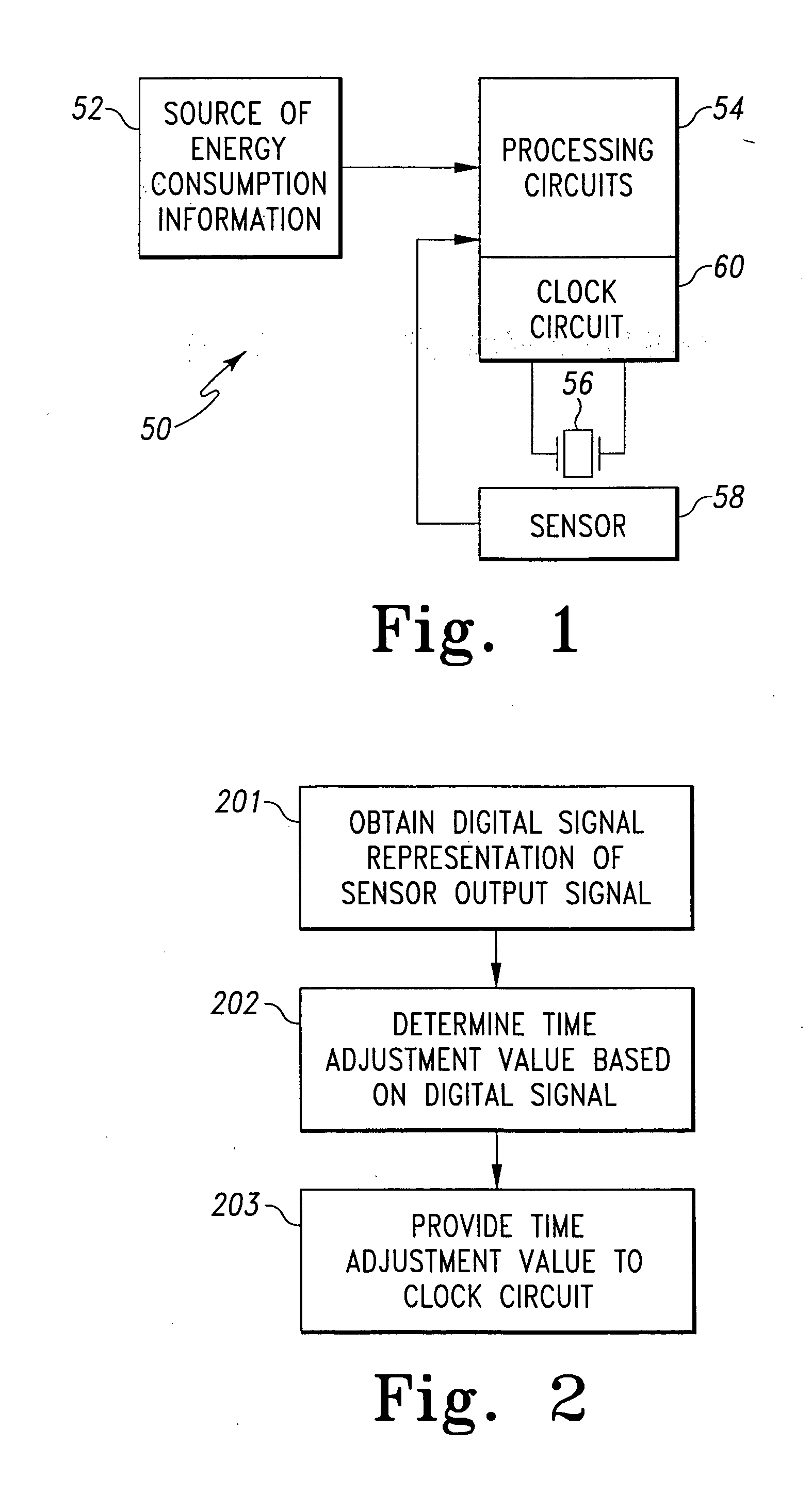
[0022]FIG. 1 shows a block diagram schematic representation of a utility meter 50 that includes a time keeping function. The time keeping function preferably includes a real-time clock that is used to generate time-dependent metering information. Time dependent metering information may include commodity consumption methods over predetermined periods of time, or using time-dependent commodity consumption rates.

[0023]In accordance with the present invention, the utility meter 50 includes comprises a source of energy consumption information 52, a processing circuit 54, a temperature dependent time keeping component 56, a sensor 58, and a clock circuit 60.

[0024]In general, the time keeping component 56 and the clock circuit 60 perform the time keeping function of the meter 50. To this end, the time keeping component 56 may suitably be a crystal oscillator or other device that generates timing signals from which a clock may be maintained. The clock circuit 60, which may suitably be carri...


PUM

PropertyMeasurementUnit
frequencyaaaaaaaaaa
temperatureaaaaaaaaaa

Abstract

A utility meter having a temperature compensation function provides advantages such as improved time keeping accuracy. According to an exemplary embodiment, a utility meter includes at least one sensor for detecting an ambient temperature at a location corresponding to a component such as a crystal oscillator that enables a time keeping function of the meter, and generating an output signal representative of the detected ambient temperature. A device such as a digital signal processor adjusts at least one clock maintained by the time keeping function of the meter in dependence upon the output signal from the at least one sensor.

Description

[0001]This application claims the benefit of U.S. Provisional Patent Application Ser. No. 60 / 325,074, filed Sep. 25, 2001, and which is incorporated herein by reference.FIELD OF THE INVENTION[0002]The present invention generally relates to utility meters, and more particularly, to utility meters that employ a time reference upon which at least some metering operations or metering information depend.BACKGROUND OF THE INVENTION[0003]Utility meters are devices that, among other things, measure the consumption of a utility provided commodity, such as electric energy, gas, or water, by a residence, factory, commercial establishment or other such facility. Utility service providers, or simply utilities, employ utility meters to track individual customers' usage of utility provided commodities. Utilities track customer usage for many purposes, including billing and tracking demand for the relevant consumed commodity.[0004]Utilities are frequently required by state or local regulations or b...

Claims


Application Information

Patent Timeline
Patent Type & Authority Applications(United States)
IPC IPC(8): G01R22/06G01K13/00
CPCG01R22/10G01K13/00
Inventor SLATER, BYRON J.VOISINE, JOHN T.
Owner LANDIS GYR LLC
Learn More