Microwave and Millimeter Frequency Bistatic Radar Tracking and Fire Control System

a radar and microwave technology, applied in active radio relay systems, using reradiation, instruments, etc., can solve problems such as handoff problems, transmitters may be detected from a great distance, and enemies may easily determine their location

Inactive Publication Date: 2008-02-21
USA REPRESENTED BY THE SEC OF THE NAVY
View PDF7 Cites 22 Cited by
  • Summary
  • Abstract
  • Description
  • Claims
  • Application Information

AI Technical Summary

Problems solved by technology

This radar has the disadvantage that the transmitter may be detected from a great distance.
If used in a military vehicle or aircraft an enemy may easily determine its location.
It is possible to have gaps as large as 15 to 20 minutes, creating a handoff problem from one satellite to the next.

Method used


Image

  • Microwave and Millimeter Frequency Bistatic Radar Tracking and Fire Control System
  • Microwave and Millimeter Frequency Bistatic Radar Tracking and Fire Control System
  • Microwave and Millimeter Frequency Bistatic Radar Tracking and Fire Control System

Examples


Embodiment Construction

[0007] Before explaining the disclosed embodiments of the present invention in detail it is to be understood that the invention is not limited in its application to the details of the particular arrangement shown since the invention is capable of other embodiments. Also, the terminology used herein is for the purpose of description and not of limitation. In the figures, the same reference numbers are used to identify the same components.

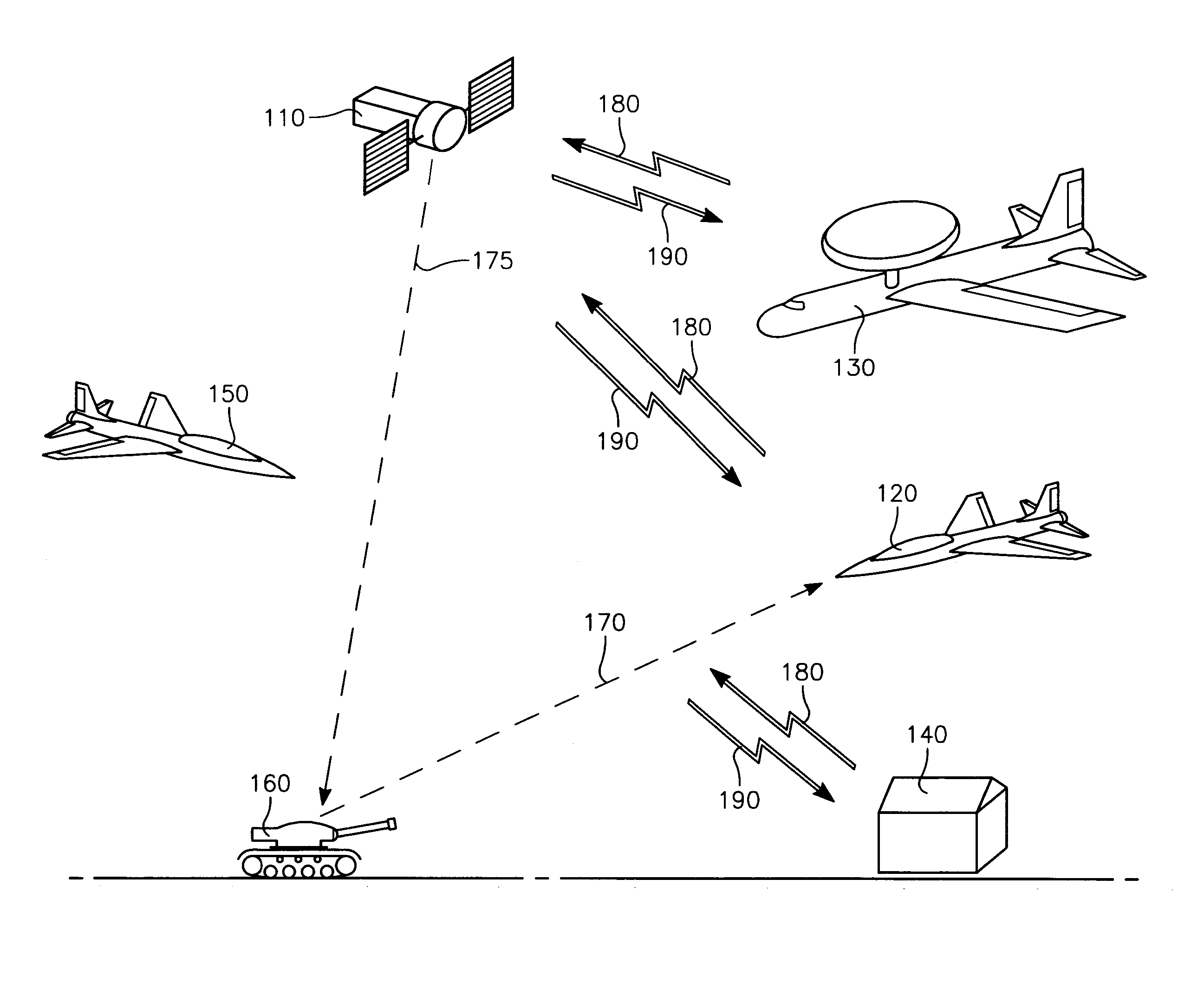
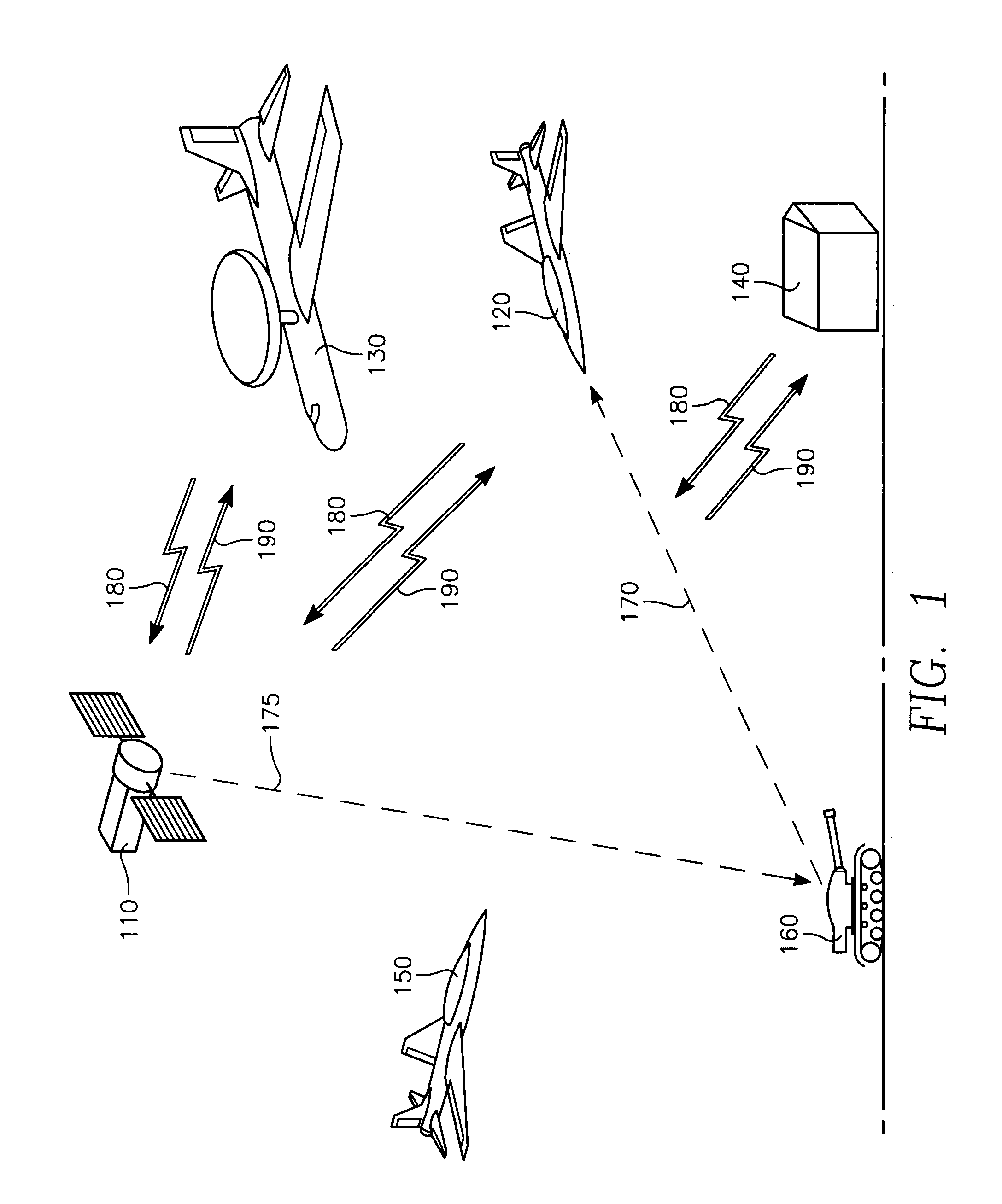
[0008] Embodiments of the invention include a system and a method for tracking and computing a firing solution for at least one target utilizing bistatic radar. A phased array antenna shall be constructed upon a satellite platform in a geosynchronous orbit with the earth. A radar transmitter shall illuminate a selected area of the earth. A receiving antenna shall receive reflected energy (signal) from targets illuminated. Targets in the illuminated area shall be tracked over time, enabling a fire control solution to be computed for the target(s). Th...


PUM


Abstract

A bistatic passive radar system for tracking at least one target utilizing means for transmitting radar signals from at least one satellite platform in a geosynchronous orbit with the earth, means for receiving radar signals from a reflection from each target, means for tracking a position of each target over time, and means for computation of a fire control solution of each target.

Description

CROSS-REFERENCE TO RELATED APPLICATIONS [0001] This is a continuation application, claiming the benefit of a parent application, Ser. No. 11 / 174,209 filed on Jun. 30, 2005, whereby the entire disclosure of the parent application is incorporated herein by reference.STATEMENT REGARDING FEDERALLY SPONSORED RESEARCH OR DEVELOPMENT [0002] The invention described herein may be manufactured and used by or for the government of the United States of America for governmental purposes without the payment of any royalties thereon or therefore.BACKGROUND OF THE INVENTION [0003] Ordinary (monostatic) radar systems have to transmitter and receiver co-located on the same platform. This radar has the disadvantage that the transmitter may be detected from a great distance. If used in a military vehicle or aircraft an enemy may easily determine its location. Bistatic radar was developed wherein the transmitter and receiver are located separately, allowing the vehicle or aircraft to receive only and th...

Claims


Application Information

Patent Timeline
Patent Type & Authority Applications(United States)
IPC IPC(8): G01S13/48H01Q3/24
CPCG01S13/003H01Q3/24G01S13/66G01S13/72
Inventor GHALEB, SAMKINDER, FLOYD A.
Owner USA REPRESENTED BY THE SEC OF THE NAVY
Why Eureka
Try Eureka