small arms scope

A technology for sights and light weapons, applied in the field of telescopic sights, can solve problems such as insufficient functions, and achieve the effects of reducing the size and weight of the whole machine, reducing costs, and expanding the scope of use

Active Publication Date: 2009-12-16
西安应用光学研究所
View PDF1 Cites 19 Cited by
  • Summary
  • Abstract
  • Description
  • Claims
  • Application Information

AI Technical Summary

Benefits of technology

This patented technology combines different components such as cameras, sensors, display screens, lights, radar systems, and communication equipment together on a chip (micro computer). It allows users to see both visual and radio frequency sources simultaneously without being limited by their physical location. Additionally, this integration makes them more efficient than current methods like combining multiple pieces separately. Overall, these technical features make it possible to create advanced military training tools used during warfare scenarios.

Problems solved by technology

This patented technical problem addressed by this patents relates to improving the functionality of smaller arm lights (SCI) without compromising its accuracy at long ranges. Current methods involve adding new parts such as targets or cameras onto existing systems, but they may still lack sufficient precision needed for effective training purposes.

Method used


Image

  • small arms scope
  • small arms scope
  • small arms scope

Examples


Embodiment Construction

[0016] The present invention will be further described in detail below in conjunction with the accompanying drawings and preferred embodiments.

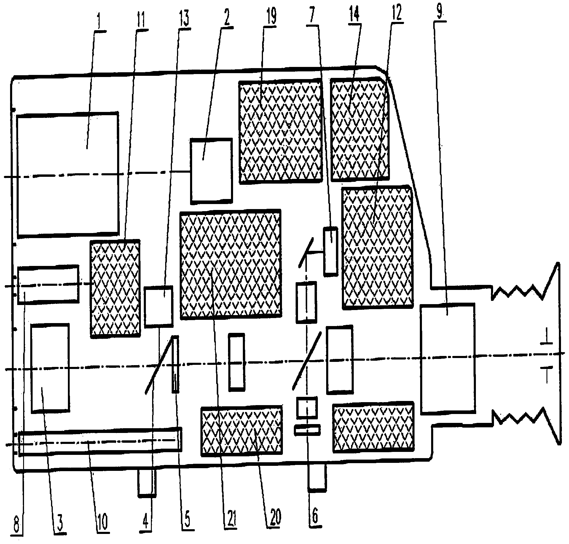
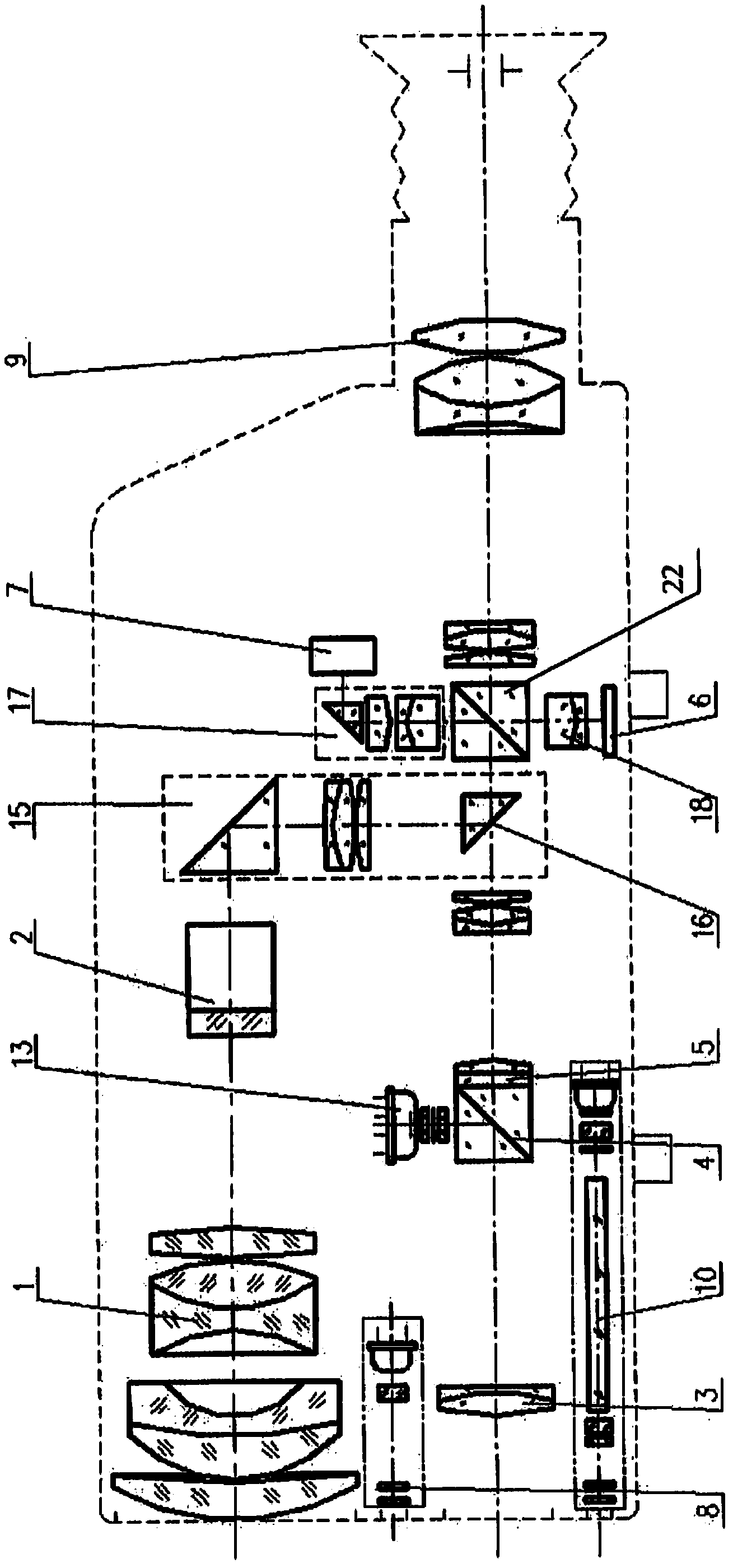
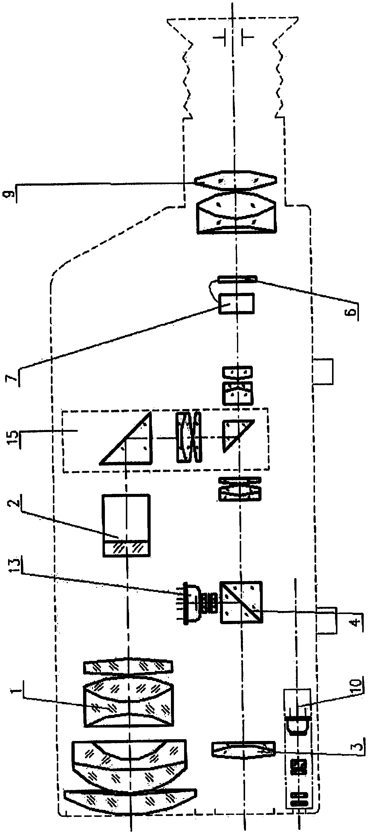
[0017] as figure 1 , figure 2 As shown, the day-vision aiming channel of the first preferred embodiment of the present invention includes a day-vision objective lens 3 , a first dichroic prism 4 , a reticle 5 , and an eyepiece 9 . The day-vision objective lens 3 is a group of imaging objective lenses, which is not only the imaging channel for daytime observation and aiming, but also the collection channel for the reflected signal of the laser ranging beam. The first beam-splitting prism 4 is a cubic prism, and its 45° beam-splitting surface is coated with a beam-splitting film that reflects 1.06 μm laser light and transmits 0.40-0.90 μm visible light. The reflectivity is greater than 90%, and the transmittance is greater than 90%. The reticle 5 is used for aiming at the target when looking directly at the target. The aiming scale ...


PUM


Abstract

The invention discloses a light weapon scope. The sight integrates multiple functions, not only integrates day vision and night vision aiming channels, realizes conventional day and night direct-viewing and aiming functions, but also integrates camera devices and micro-displays to realize TV viewing and aiming functions, TV images It can be observed directly through the eyepiece or indirectly through an external monitor. In addition, the present invention can also integrate laser ranging components, wireless transmitting components, laser irradiators, and radio frequency receiving components, thereby realizing functions such as fire control, wireless transmission of data and video images, indicating targets for night vision targeting channels, and identifying friend or foe. The main advantage of the present invention is that it has relatively complete functions, various combination forms, relatively small volume and weight, and can be used not only as a gun sight, but also as a fire control system for small-caliber artillery.

Description


Claims


Application Information

Patent Timeline
Owner 西安应用光学研究所
Why Eureka
Try Eureka