
Metal part manufacturing system and method adopting micro-casting-forging and milling-grinding in-situ composite

An in-situ composite technology for metal parts, applied in the field of metal parts manufacturing, can solve problems such as poor surface quality, uneven structure, large residual stress, etc., and achieve good processing quality, reduce residual stress, and small ultrasonic cutting force.

Inactive Publication Date: 2019-08-02
HUAZHONG UNIV OF SCI & TECH
View PDF9 Cites 46 Cited by
  • Summary
  • Abstract
  • Description
  • Claims
  • Application Information

AI Technical Summary

Problems solved by technology

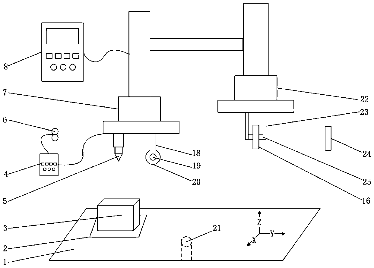
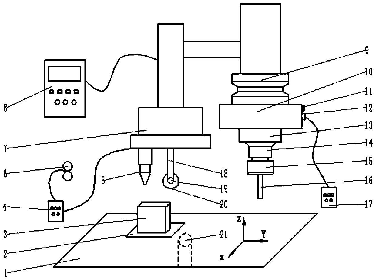
[0005] Aiming at the above defects or improvement needs of the prior art, the present invention provides a metal part manufacturing system and method that combines micro-casting, forging, milling and grinding in situ. Simultaneous rolling and rolling in the fused deposition process, combined with milling and grinding processes, can solve the problems of uneven structure, serious deformation, large residual stress, poor structure performance and poor surface quality in the additive manufacturing of metal parts

Method used


Image

  • Metal part manufacturing system and method adopting micro-casting-forging and milling-grinding in-situ composite
  • Metal part manufacturing system and method adopting micro-casting-forging and milling-grinding in-situ composite
  • Metal part manufacturing system and method adopting micro-casting-forging and milling-grinding in-situ composite

Examples


Embodiment 1

[0051] use as figure 1 In the system shown, the selected raw material is titanium alloy TC4-DT, the shape of the raw material is metal wire, and the supply method is wire-feeding, which specifically includes the following steps:

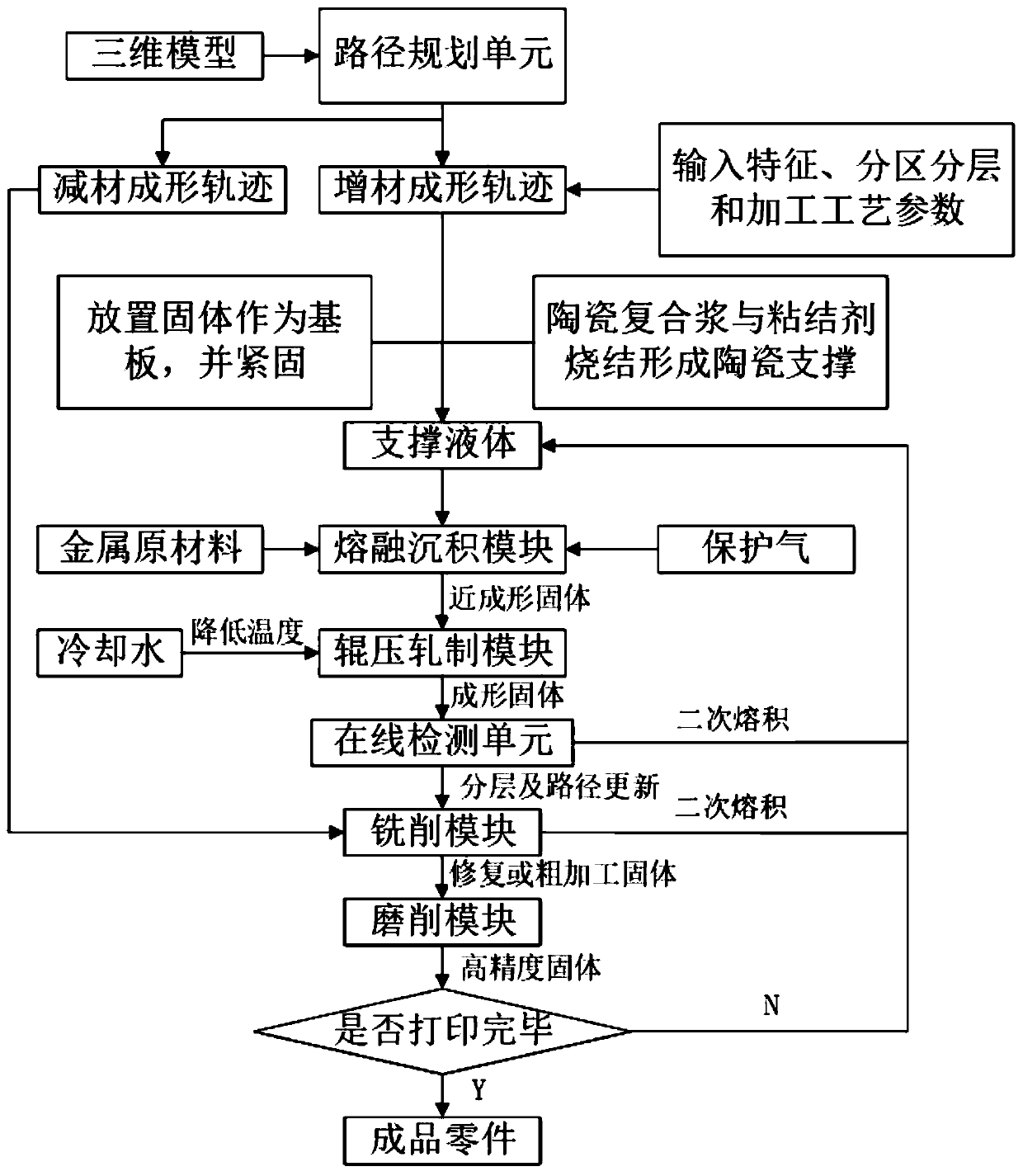
[0052] S1 generates the subtractive forming trajectory and additive forming trajectory suitable for the part structure through the 3D CAD model and features, partitioning and layering, and processing parameters of the metal part to be formed;

[0053] S2 Thoroughly clean the substrate and metal wire to remove moisture, impurities and oxide film, so that the entire manufacturing space is sealed by the atmosphere chamber and filled with helium-argon mixed gas to prevent the molten metal from being oxidized;

[0054] The heat source type of S3 melting heat source is arc heat source, Fronius welding power source CMT Advanced 4000 is used, and the matching wire feeding mechanism VR 7000 CMT is selected as the feeding mechanism to melt the metal wire, and ...

Embodiment 2

[0059] use as figure 1 In the system shown, the selected raw material is titanium alloy TC4-DT, the shape of the raw material is metal wire, and the supply method is wire-feeding, which specifically includes the following steps:

[0060] S1 to S5 are identical with embodiment 1;

[0061] The S6 grinding tool adopts the grinding wheel, which replaces the milling cutter with the grinding wheel, and grinds the surface of the formed part whose defect and shape meet the manufacturing standard after milling, so as to improve the surface accuracy of the part;

[0062] S7 repeats S3 to S6 until the processing and manufacturing of the entire metal part is completed.

Embodiment 3

[0064] use as figure 2 In the system shown, the selected raw material is titanium alloy TC4, the shape of the raw material is metal wire, and the supply method is wire-feeding, which specifically includes the following steps:

[0065] S1 generates the subtractive forming trajectory and additive forming trajectory suitable for the part structure through the 3D CAD model and features, partitioning and layering, and processing parameters of the metal part to be formed;

[0066] S2 Thoroughly clean the substrate and metal wire to remove moisture, impurities and oxide film, so that the entire manufacturing space is sealed by the atmosphere chamber and filled with helium-argon mixed gas to prevent the molten metal from being oxidized;

[0067]The heat source type of S3 melting heat source is arc heat source, Fronius welding power supply CMT Advanced 4000 is used, and the matching wire feeding mechanism VR 7000 CMT is selected as the feeding mechanism to melt the metal wire, and the...


PUM


Abstract

The invention belongs to the field of metal part manufacturing, and particularly discloses a metal part manufacturing system and method adopting the micro-casting-forging and milling-grinding in-situcomposite. The system involves a micro-casting-forging module, a milling module, a five-axis linkage workbench and a control device, wherein the micro-casting-forging module is connected with the milling module and comprises a fusion deposition sub-module and a roller-pressing rolling sub-module, the five-axis linkage workbench is positioned below the micro-casting-forging module and the milling module, and is used for containing metal parts to be formed, and the control device is connected with the fusion deposition sub-module, the roller-pressing rolling sub-module, the milling module and the five-axis linkage workbench. According to the system and method, micro-casting-forging and a milling process are composited to process and manufacture the metal parts, so that the problems that whenthe metal parts are made through the additive manufacturing, the structure is not uniform, the deformation is serious, the residual stress is large, the structure performance is poor, and the surfacequality is poor are solved, and the system and method is especially suitable for processing a high-performance complicated special-shaped element.

Description

technical field [0001] The invention belongs to the field of metal part manufacturing, and more specifically relates to a metal part manufacturing system and method for micro-casting, forging, milling and grinding in-situ composite. Background technique [0002] The traditional manufacturing process of metal parts is mainly through casting or forging, combined with turning, milling, grinding and other mechanical subtractive processing to obtain parts that meet the quality and precision requirements, but there are problems such as long processing cycle, low material utilization rate, and high manufacturing cost. Especially for the manufacture of large and complex parts, such as the reducer casing of the aero-engine transmission system, which has a complex outer surface, inner cavity, inner hole, and inner flow channel, and is a complex special-shaped structural part, while the high-temperature alloy casing is a whole It is a ring-shaped structure with bosses and small holes o...

Claims


Application Information

Patent Timeline
Patent Type & Authority Applications(China)
IPC IPC(8): B23P23/00B23P23/04B22F3/115B33Y10/00B33Y30/00
CPCB22F3/115B23P23/00B23P23/04B33Y10/00B33Y30/00
Inventor 来五星蔡建德梁飞宇张海鸥王桂兰
Owner HUAZHONG UNIV OF SCI & TECH
Learn More