Projection display system with pressure sensing at a screen, a calibration system corrects for non-orthogonal projection errors

a projection display system and pressure sensing technology, applied in the field of interactive display systems, can solve the problem that no system has been provided for integrating large-scale image projection with data input in an interactive manner

Inactive Publication Date: 2008-02-21
SMART TECH INC (CA)
View PDF48 Cites 76 Cited by
  • Summary
  • Abstract
  • Description
  • Claims
  • Application Information

AI Technical Summary

Benefits of technology

[0006] According to the present invention, an interactive display system is provided in which a touch-sensitive screen, or white board, is used as a projection surface. Control signals are generated by the touch-sensitive screen in the usual manner responsive to user applied pressure (e.g. due to drawing on the board with a marker, pointer, stylus or finger, etc.). At the same time, a computer is used to execute any one or more well known applications programs, in the usual manner. However, according to the present invention, the computer generated screen is projected onto the touch-sensitive screen utilizing an LCD projector panel in conjunction with an overhead projector. Furthermore, according to the present invention, control signals received from the touch-sensitive screen are integrated with the computer generated graphics so as to be projected therewith onto the touch-sensitive screen. In this way, a completely interactive display system is provided in which the user can highlight and edit information generated by the computer program by simply drawing on the touch-sensitive screen. Thus, the system of the present invention provides a truly unique interactive approach to giving group presentations.

Problems solved by technology

Although such prior art devices are useful for displaying information and inputting data into a computer, it is believed that no system has hitherto been provided for integrating large scale image projection with data input in an interactive manner.

Method used


Image

  • Projection display system with pressure sensing at a screen, a calibration system corrects for non-orthogonal projection errors
  • Projection display system with pressure sensing at a screen, a calibration system corrects for non-orthogonal projection errors
  • Projection display system with pressure sensing at a screen, a calibration system corrects for non-orthogonal projection errors

Examples


Embodiment Construction

[0040] The principles of the invention are demonstrated in accordance with the following preferred embodiments.

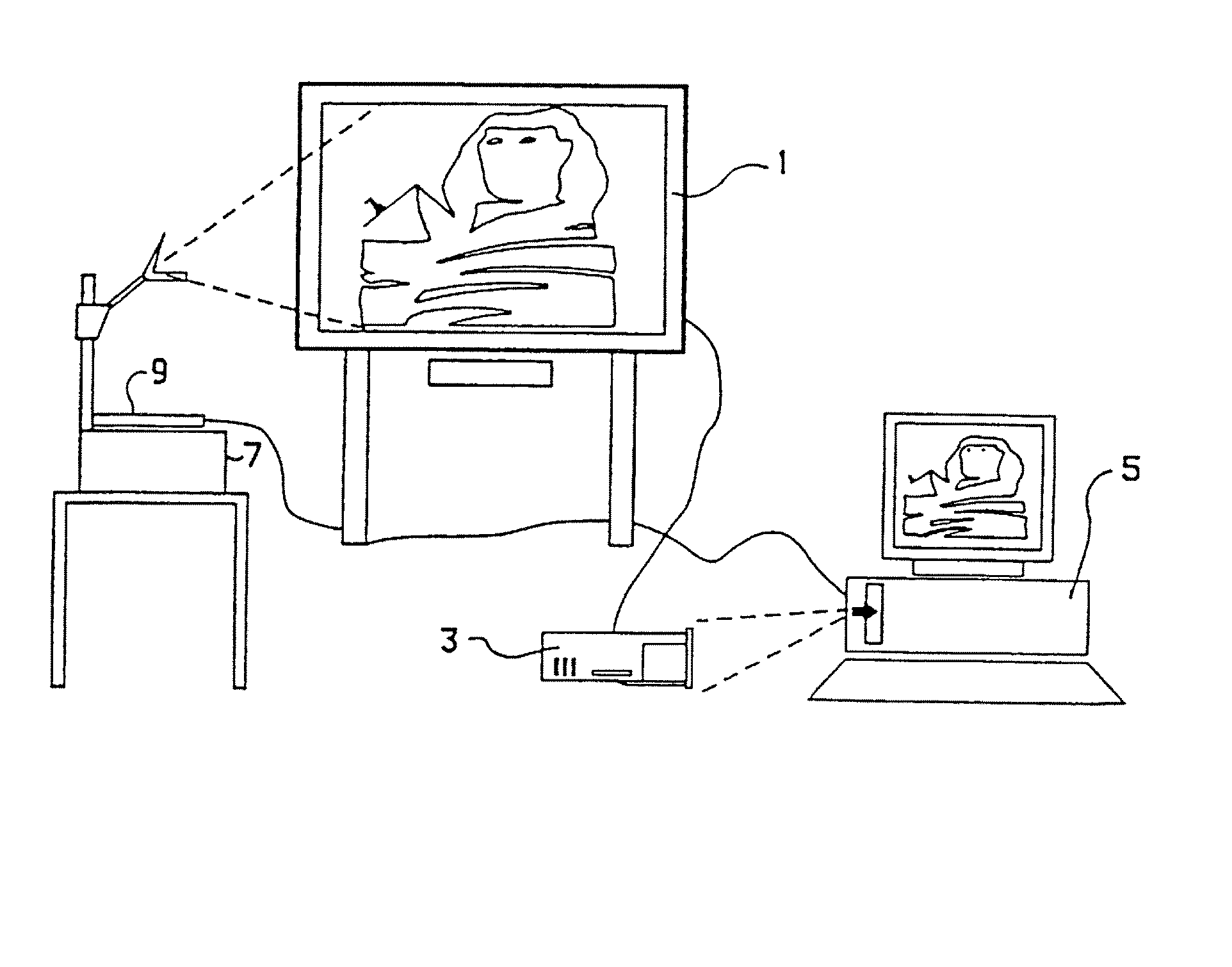
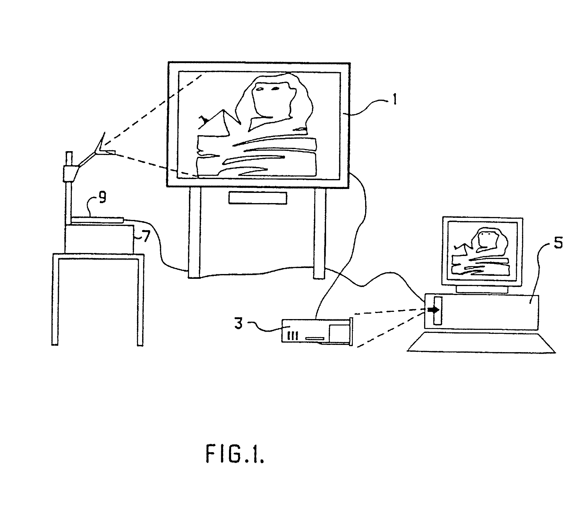
[0041] The interactive graphics system of the present invention is shown in general with reference to FIG. 1, comprising a touch-sensitive screen 1 having an output connected to an input of an electronic touch screen controller 3 installed within a card slot of a personal computer 5.

[0042] An overhead projector 7 is orientated so as to project an image onto the surface of touch-sensitive screen 1. The image is generated by means of LCD projector panel 9 which is connected to the graphics output of the personal computer 5.

[0043] In addition to executing one or more well known applications programs (e.g. Word Processing, Spreadsheet, Graphics, etc.), according to the present invention personal computer 5 also executes a graphics translator routine for receiving coordinate or location information from the touch-sensitive screen 1 and in response interacting with the drawing...


PUM


Abstract

Calibration structure, method, and code for correcting non-orthogonal misalignment of a computer-generated image that is projected onto a large screen touch-detecting display, so that a computer-generated image appears substantially where the display is touched. Structure / method / code generates at least four calibration marks, respectively, substantially proximate four corners of a projected image to be displayed on the display. Structure / method / code, responsive to a touch on the large screen touch-detecting display where each of the four calibration marks is displayed, identifies horizontal and vertical coordinates of each touched location. Structure / method / code calibrates the projected image to the display after the four calibration marks have been touched. Structure / method / code, responsive to another touch on the display after calibration, displays a computer image substantially at the location of the another touch.

Description

[0001] This application is a continuation of U.S. application Ser. No. 10 / 832,281, filed Apr. 27, 2004 (allowed), which is a continuation of U.S. application Ser. No. 09 / 989,154, filed Nov. 21, 2001, (now U.S. Pat. No. 6,747,636, issued Jun. 8, 2004), which is a continuation of Ser. No. 09 / 595,976, filed Jun. 16, 2000, (now U.S. Pat. No. 6,337,681, issued Jan. 8, 2002), which is a continuation of U.S. application Ser. No. 08 / 477,498, filed Jun. 7, 1995, (now U.S. Pat. No. 6,141,000, issued Oct. 31, 2000), which is a continuation of U.S. application Ser. No. 07 / 780,052, filed Oct. 21, 1991, (now U.S. Pat. No. 5,448,263, issued Sep. 5, 1995), the contents of all of which are incorporated herein by reference.FIELD OF THE INVENTION [0002] This invention relates in general to display systems and more particularly to an interactive display system for projecting user drawn script in combination with screen output of application programs onto a touch sensitive display surface which is capab...

Claims


Application Information

Patent Timeline
Patent Type & Authority Applications(United States)
IPC IPC(8): G06F3/041G03B21/132G06F3/033H04L12/18
CPCG03B21/132G06F3/033G06F3/0418H04L12/1831H04L12/1813H04L12/1822G06F3/0488
Inventor MARTIN, DAVID A.
Owner SMART TECH INC (CA)
Why Eureka
Try Eureka