Light emitting unit and light guiding element thereof

a technology of light emitting units and light guiding elements, which is applied in the direction of planar/plate-like light guides, lighting and heating apparatuses, instruments, etc., can solve the problems of deteriorating and achieve the effect of enhancing the quality of light emitting units and lengthening the light mixing distan

Inactive Publication Date: 2008-02-21
GIGNO TECH CO LTD
View PDF7 Cites 9 Cited by
  • Summary
  • Abstract
  • Description
  • Claims
  • Application Information

AI Technical Summary

Benefits of technology

[0010]In view of the foregoing, the invention is to provide a light emitting unit capable of lengthening a light mixing distance effectively and enhancing the uniformity of the mixed light, and a light guiding element thereof.
[0014]As mentioned above, a light emitting portion, a reflecting portion and a light mixing portion of the light guiding element are provided to lengthen the light mixing distance in the light emitting unit and the light guiding element thereof according to the invention. The reflecting portion having one reflecting surface is connected to one side of the light emitting portion, and the light mixing portion is connected to the reflecting portion and forms an included angle with the light emitting portion. Also, the light mixing portion is disposed on each of the light emitting elements, and the light rays outputted from the light emitting elements enter the light mixing portion. Compared with the related art, the light mixing portion mixes the light rays outputted from the light emitting elements, and then the reflecting portion reflects the mixed light rays to the light emitting portion in the light emitting unit and the light guiding element thereof. The light rays may be mixed in the light mixing portion as well as the reflecting portion and the light emitting portion, and finally emitted from the light emitting portion. In this manner, the light mixing distance may be effectively lengthened, and the mixed light rays may become more uniform so that the quality of the light emitting unit may be enhanced.

Problems solved by technology

In the above-mentioned structure of the light emitting unit 1, the different colors of light rays outputted from the light emitting elements 13 cannot be sufficiently mixed or may become non-uniform so that the quality of the light emitting unit 1 is deteriorated because the light mixing distance is not long enough.

Method used


Image

  • Light emitting unit and light guiding element thereof
  • Light emitting unit and light guiding element thereof
  • Light emitting unit and light guiding element thereof

Examples


Embodiment Construction

[0023]The present invention will be apparent from the following detailed description, which proceeds with reference to the accompanying drawings, wherein the same references relate to the same elements.

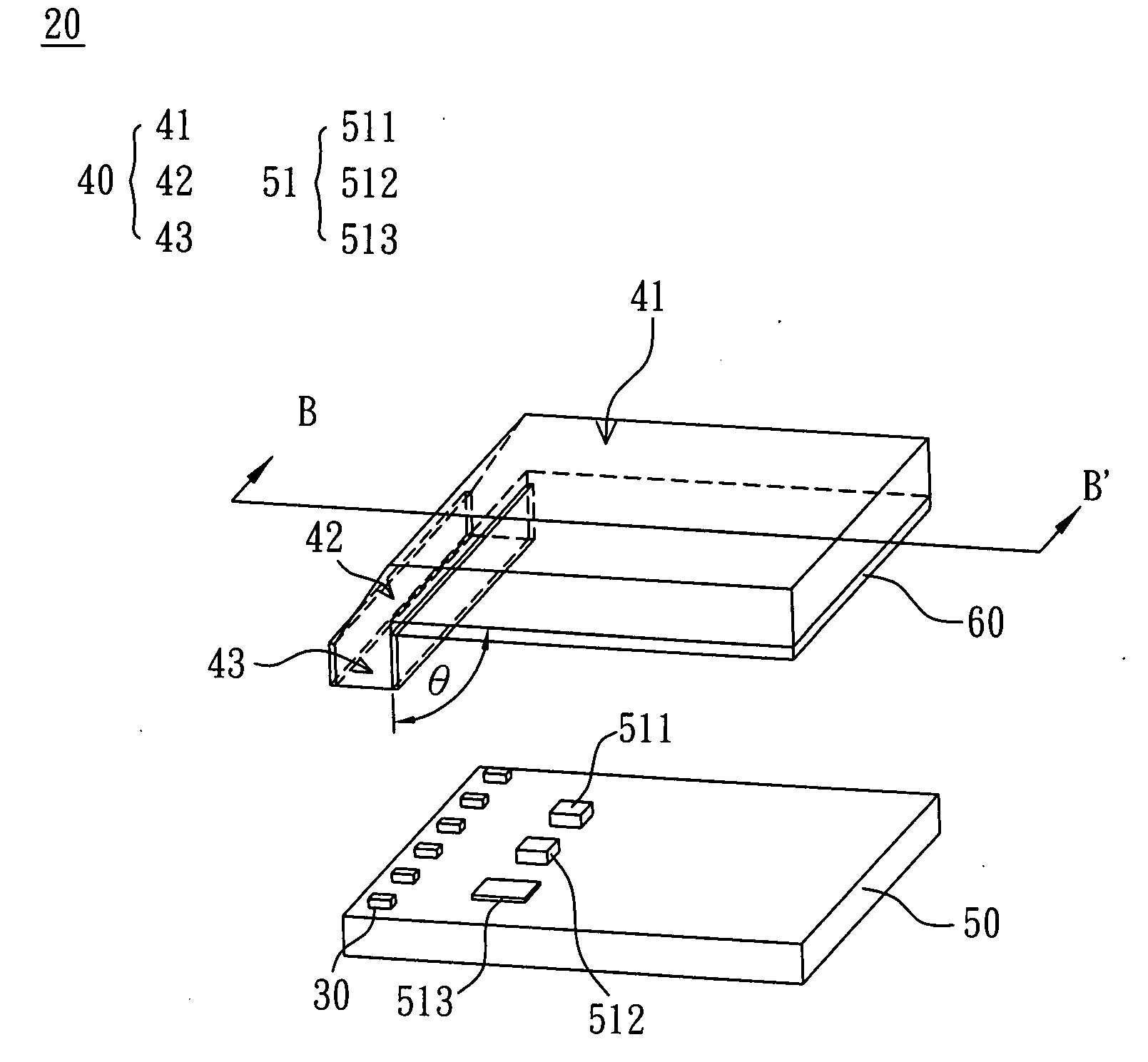
[0024]Please refer to FIGS. 3 and 4 simultaneously, wherein FIG. 4 is a schematically cross-sectional view taken along a line B-B of FIG. 3. A light emitting unit 20 according to the preferred embodiment of the invention includes a plurality of light emitting elements 30 and a light guiding element 40. The light emitting unit 20 of this embodiment is not particularly restricted, and may be implemented as an illumination device used in the daily life or a backlight module used in a liquid crystal display (LCD). Herein, the light emitting unit 20 is the backlight module.

[0025]In this embodiment, the light emitting element 30 is not particularly restricted and may be implemented as including a light emitting diode (LED), a LED array or a cold cathode fluorescent lamp (CCFL). Herein, the ...


PUM


Abstract

A light guiding element includes a light emitting portion, a reflecting portion and a light mixing portion. The reflecting portion has a reflecting surface, the reflecting portion is connected to one side of the light emitting portion, and the light mixing portion is connected to the reflecting portion and forms an included angle with the light emitting portion. A light emitting unit is also disclosed.

Description

CROSS REFERENCE TO RELATED APPLICATIONS[0001]This Non-provisional application claims priority under 35 U.S.C. §119(a) on Patent Application No(s). 095130153 filed in Taiwan, Republic of China on Aug. 16, 2006, the entire contents of which are hereby incorporated by reference.BACKGROUND OF THE INVENTION[0002]1. Field of Invention[0003]The invention relates to a light emitting unit and a light guiding element thereof, and, in particular, to a light emitting unit capable of lengthening a light mixing distance, and a light guiding element thereof.[0004]2. Related Art[0005]With the coming of the digital age, the technology for the liquid crystal display (LCD) device also has grown rapidly, and the LCD device has become an indispensable electronic product. Thus, the requests on the technology and the function of the LCD device have become higher and higher.[0006]In general, the LCD device mainly includes a LCD panel and a backlight module. The LCD panel mainly has two substrates and a liq...

Claims


Application Information

Patent Timeline
Patent Type & Authority Applications(United States)
IPC IPC(8): F21V8/00F21V7/04
CPCG02B6/0018G02B6/0028G02B6/0068G02F1/133609G02B6/0083G02F1/133603G02B6/0078
Inventor LIN, FENG-LI
Owner GIGNO TECH CO LTD
Why Eureka
Try Eureka