A led plant growth light

A plant growth lamp and LED lamp bead technology, applied in the field of growth lamps, can solve the problems of uneven light output and uneven distribution of light quantum flux density of plant growth lamps, and achieve high uniformity, low lighting density, and improved uniformity. Effect

Active Publication Date: 2019-08-20
SOUTH CHINA UNIV OF TECH
View PDF5 Cites 0 Cited by
  • Summary
  • Abstract
  • Description
  • Claims
  • Application Information

AI Technical Summary

Problems solved by technology

[0003] The purpose of the present invention is to overcome the shortcomings and deficiencies of the prior art, in order to solve the problems of uneven light output and uneven distribution of light quantum flux density of existing plant growth lamps, and to provide a high-performance plant with uniform light spectrum and uniform light quantum flux density. grow lights

Method used


Image

  • A led plant growth light
  • A led plant growth light
  • A led plant growth light

Examples


Embodiment 1

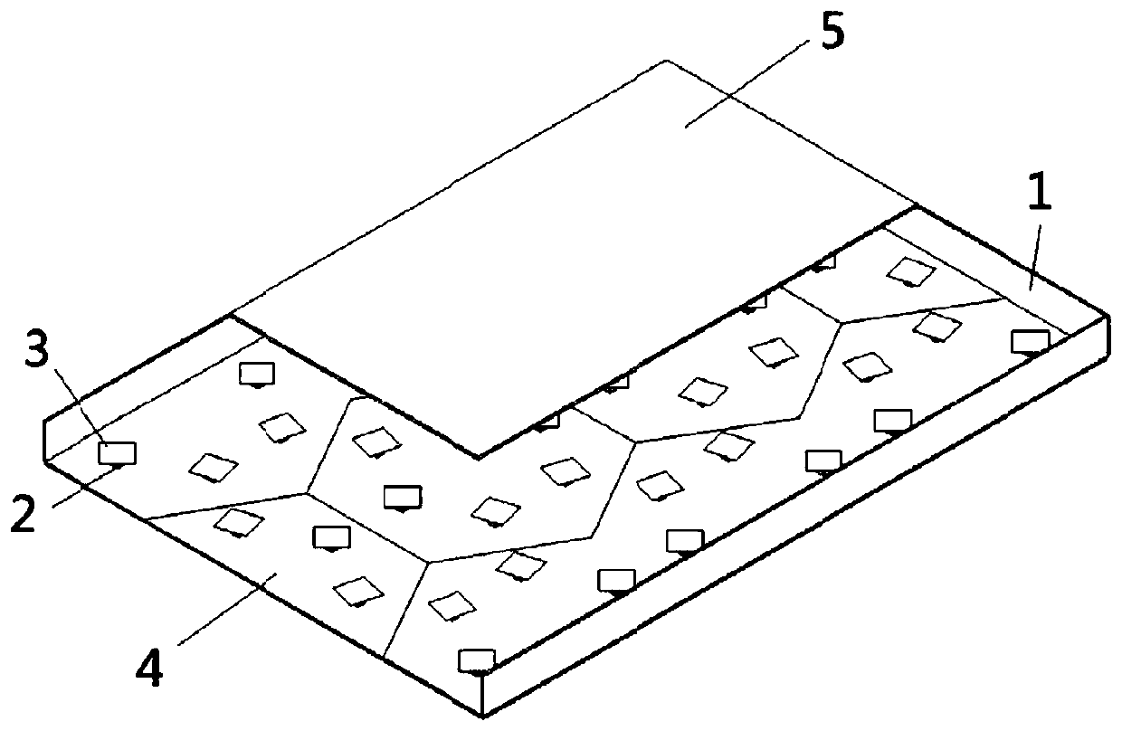
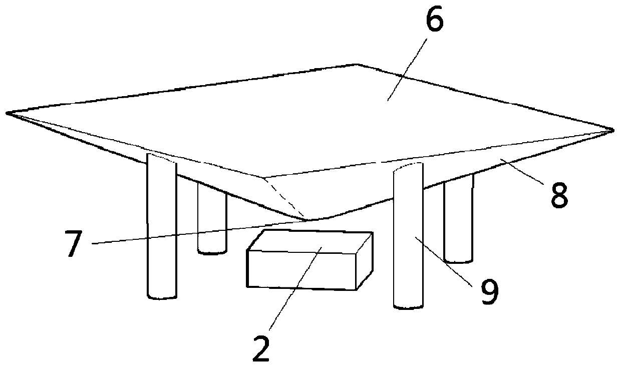
[0032] This embodiment discloses a high-performance plant growth lamp, such as figure 1 As shown, it includes housing 1, LED2, light mixing element 3, diffuse reflection bottom plate 4 and light output panel 5 and other structures, and the structure of a single light mixing element is as follows figure 2As shown, it includes structures such as an upper bottom surface 6, a lower bottom surface 7, a reflective surface 8 and a transparent bracket 9. The LEDs are arranged in a hexagonal array on the diffuse reflection base plate, and a light mixing element is installed above each LED by a transparent bracket. The light mixing element is formed by injection molding process. After protecting the upper and lower light-transmitting surfaces, vacuum evaporation is used to aluminize the reflective surface, and finally the light-transmitting surface is polished to make it transparent. The size of the whole lamp is a cube of 271mm*191mm*17, the shape of the light mixing element is a tru...

Embodiment 2

[0035] The shape of the light mixing element used in this embodiment is a truncated cone, and other structures are the same as those in the embodiment. The size of the whole lamp is 271mm*191mm*17mm. The structure of the light mixing element is as follows Figure 4 As shown, it includes an upper bottom surface 10, a lower bottom surface 11, a reflective surface 12 and a transparent bracket 13 and other structures. The radius of the upper bottom surface of the frustum-shaped light mixing element is 6mm, the radius of the lower surface is 0.35mm, the thickness of the element is 2.5mm, the height between the element and the LED is 0.7mm, the distance between the LEDs is 35mm, and the internal height of the lamp is 15mm.

Embodiment 3

[0037] The shape of the light mixing element used in this embodiment is hemispherical, and the hemispherical light mixing element is an intercepted part of a sphere. The light mixing element structure is as Figure 5 As shown, it includes structures such as an upper bottom surface 14, a lower bottom surface 15, a reflective surface 16 and a transparent bracket 17. The radius of the upper bottom surface is 4mm, the radius of the lower bottom surface is 0.6mm, the thickness of the component is 3.0mm, the height between the component and the LED is 0.7mm, the distance between the LEDs is 35mm, and the internal height of the lamp is 15mm.

[0038] The above three kinds of light mixing elements are all formed by injection molding combined with vacuum evaporation, and the upper and lower bottom surfaces are light-transmitting surfaces, and the sides are light-reflecting surfaces.


PUM


Abstract

The invention discloses an LED plant growth lamp. The LED plant growth lamp comprises a lamp shell, red LED lamp beads, green LED lamp beads, blue LED lamp beads, PMMA lamp bead light mixing elements, a diffuse reflection bottom plate and a diffuse type light outlet panel. The LED lamp beads are arranged on the diffuse reflection bottom plate, each LED lamp bead is provided with one light mixing element made of PMMA lamp beads, the side face of each light mixing element is a reflection face, the upper bottom face and the lower bottom face of each light mixing element are illuminating surfaces, and the light outlet panel is a diffusion plate. The LED light rays are subjected to diffuse reflection of the reflection faces of the light mixing elements and the diffuse reflection bottom plate, the purpose of increasing the light mixing distance is achieved through constant reflection in the lamp with the relatively small thickness, furthermore, the light mixing uniformity of the lamp is improved on the premise of controlling the thickness of the lamp, and therefore the LED plant growth lamp has the beneficial effects that the lamp can achieve the uniform light outlet effect under drive of different PMM waveforms.

Description

technical field [0001] The present invention relates to a growing light technology, in particular to an LED plant growing light. The LED plant growing light is an LED plant growing light with high light output performance, which borrows the panel light structure used in LED indoor lighting to obtain uniform lighting effects. Background technique [0002] With the rapid development of modern agriculture, as a key part of plant growth, light occupies an important position in plant factories, and LED plant light sources have also emerged as the times require, but most of the LED light sources currently used in plant factories are based on traditional The optical structure of LED lamps, such as the optical structure of LED spotlights and LED advertising lights, saves design costs, but its use in plant factories is worrying, and its light mixing effect on the target plane It is very uneven, and there will be problems of too much blue light or too much red light locally, so it is...

Claims


Application Information

Patent Timeline
Patent Type & Authority Patents(China)
IPC IPC(8): F21S8/00F21V19/00F21V5/08F21V7/22A01G7/04F21Y115/10F21Y113/17F21Y105/14F21V9/40
CPCA01G7/045F21S8/00F21V5/08F21V7/22F21V9/40F21V19/001Y02P60/14
Inventor 文尚胜马丙戌庞培元陈心雅左欣梁依倩李志均
Owner SOUTH CHINA UNIV OF TECH
Why Eureka
Try Eureka