Angle correction for camera

a technology for adjusting angles and cameras, applied in the field of angle correction for cameras, can solve the problems of difficult for the camera user to determine when the camera is oriented in undesirable directions, and the camera is difficult to determine when the camera is level

Inactive Publication Date: 2008-02-21
SONY ERICSSON MOBILE COMM AB
View PDF16 Cites 32 Cited by
  • Summary
  • Abstract
  • Description
  • Claims
  • Application Information

AI Technical Summary

Problems solved by technology

It is sometimes difficult for a camera user to determine when a camera is level, especially when handling a small camera, such as a camera in a mobile phone.
It may also difficult for the camera user to determine when the camera is oriented in undesirable directions.

Method used


Image

  • Angle correction for camera
  • Angle correction for camera
  • Angle correction for camera

Examples


process 400

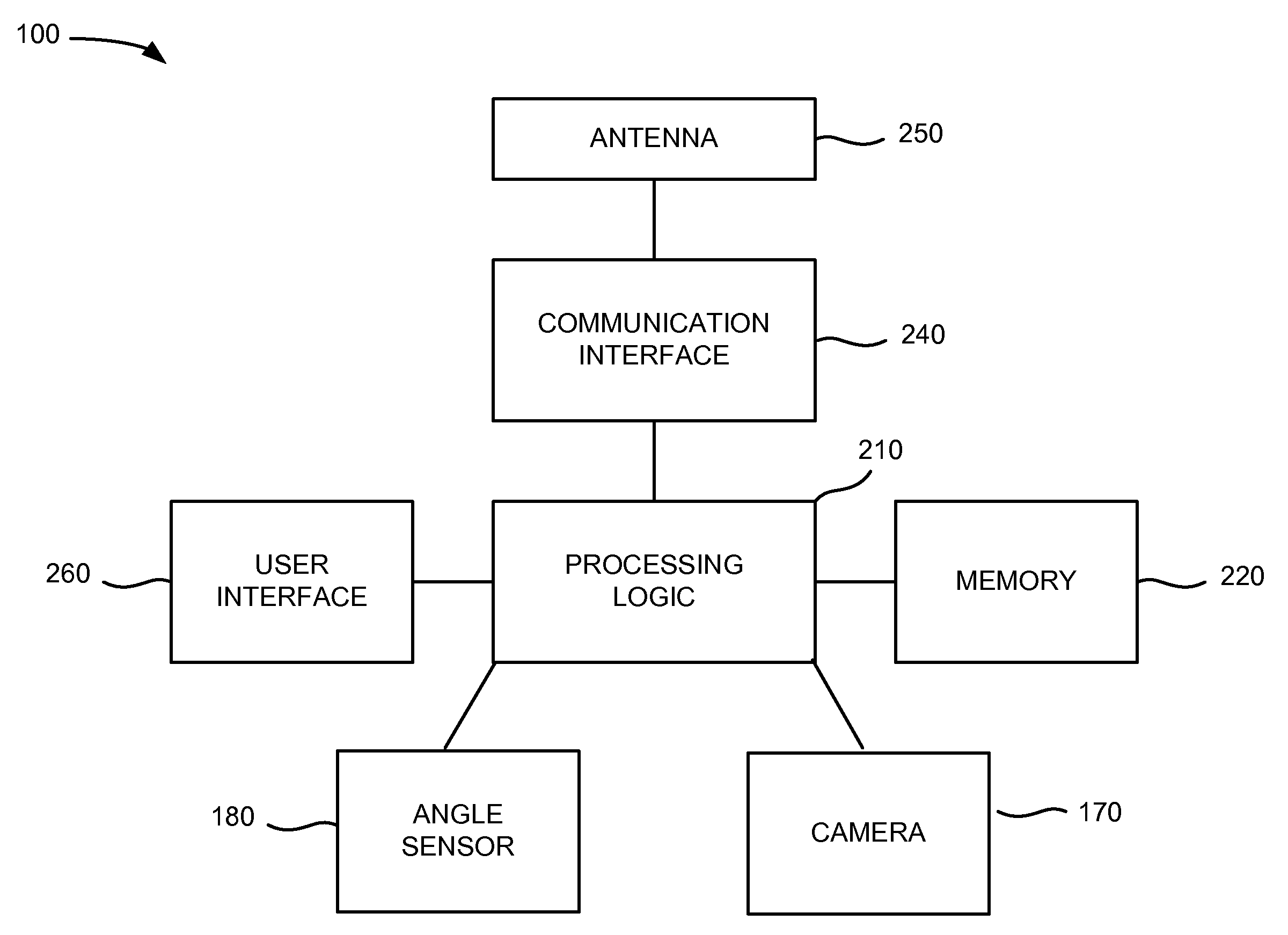
[0053]Process 400 of FIG. 4 may be performed by camera application program 304 and angle correction application program 306 running in memory 220 of device 100. Although process 400 in FIG. 4 shows blocks 402-408 in a particular order, process 400 is not limited to blocks 402-408 being in this particular order. For example, displacement angle 514 may be measured before capturing image 502, after capturing image 502, or during capturing of image 502. Displacement angle 514 may indicate the angle of displacement “when” capturing image 502. As used herein, “when capturing image 502” means approximately when capturing image 502. For example, sensor 180 measures displacement angle 514“when capturing image 502,” meaning that sensor 180 may measure displacement angle 514 soon before capturing the image, soon after capturing the image, or during capturing of image 502.

[0054]In process 400 of FIG. 4, the rotated image may be stored in memory 220, for example. In one embodiment, captured imag...


PUM


Abstract

A device may include a camera to capture an image; a sensor to measure, when the camera captures the image, information indicative of an angular displacement, about a line of sight of the camera, of an orientation of the device away from a reference orientation of the device; storage to store the measured information for rotating the image relative to a frame of the image based on the angular displacement.

Description

RELATED APPLICATIONS [0001]This application claims priority under 35 U.S.C. §119 based on U.S. Provisional Application Ser. No. 60 / 822,813, filed Aug. 18, 2006, the disclosure of which is incorporated herein by reference.BACKGROUND[0002]1. Related Field[0003]Embodiments described herein relate generally to angle correction for a camera.[0004]2. Description of Related Art[0005]It is sometimes difficult for a camera user to determine when a camera is level, especially when handling a small camera, such as a camera in a mobile phone. As a result, an image captured by the camera may have a “tilted horizon,” e.g., the horizon is not level or square with the frame of the image. It may also difficult for the camera user to determine when the camera is oriented in undesirable directions.SUMMARY[0006]In one aspect, a device is provided. The device may include a camera to capture an image; a sensor to measure information indicative of an angular displacement, about a line of sight of the came...

Claims


Application Information

Patent Timeline
Patent Type & Authority Applications(United States)
IPC IPC(8): G03B17/00
CPCH04N5/232H04N23/80H04N23/00
Inventor WERNERSSON, MATS
Owner SONY ERICSSON MOBILE COMM AB
Why Eureka
Try Eureka