Image monitoring apparatus

a monitoring apparatus and image technology, applied in the field of image monitoring apparatus, can solve the problems of difficult to recognize the positional relationship between the whole radar coverage and the zooming area, difficult to present radar images with different reference directions in the individual windows to meet specific requirements, and overwrite the entire screen image, etc., to achieve the effect of easy recognition of situations

Inactive Publication Date: 2000-07-04
FURUNO ELECTRIC CO LTD
View PDF6 Cites 23 Cited by
  • Summary
  • Abstract
  • Description
  • Claims
  • Application Information

AI Technical Summary

Benefits of technology

With this image monitoring apparatus, it is possible to use one display window to monitor a target image in relation to the ship's forward direction and the other display window to monitor a target image in relation to a predetermined reference direction. In addition, the image presented in the smaller display window allows an operator to easily recognize situations over the large monitoring area while the image shown in the larger display window enables detailed observation of the target objects detected within the zooming area.

Problems solved by technology

When the zoom function is executed on the conventional radar, however, the on-screen image is entirely overwritten.
The zoom function of the prior art has, therefore, been associated with a problem that it is difficult to recognize a positional relationship between the whole radar coverage and the zooming area.
In other words, it has been impossible to present radar images with different reference directions in the individual windows to meet specific requirements.
It has not been possible for either the conventional scanning sonar or course plotting device to show a plurality of windows on a single screen and present part of an image shown on one window on another window.

Method used


Image

  • Image monitoring apparatus
  • Image monitoring apparatus
  • Image monitoring apparatus

Examples


first embodiment

A radar according to the invention is now described with reference to FIGS. 3 to 13.

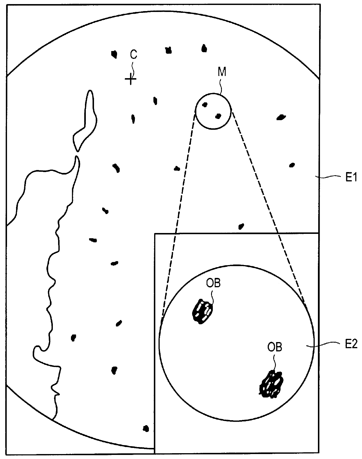
FIG. 3 is a diagram showing an example of a picture displayed by the radar of the first embodiment, in which the area designated by E1 is a display area covering about 3 / 4 of the full screen while the area designated by E2 is a display area taking up about 1 / 4 lower-right portion of the full screen. The display area E1 presents a radar image including echoes of land masses, surrounding target ships and other objects on a specific range scale with an observer's own ship located at the center of the screen. The display area E2 presents an enlarged view of a particular area of interest (zooming area) shown by a circular symbol associated with the letter M within the display area E1. In the example of FIG. 3, there are shown two targets OB detected by the radar in the display area E2. The circular symbol M marked in the display area E1 indicates to which part of the display area E1 the image enlarged in ...

second embodiment

A radar according to the invention is now described with reference to FIGS. 14 to 16.

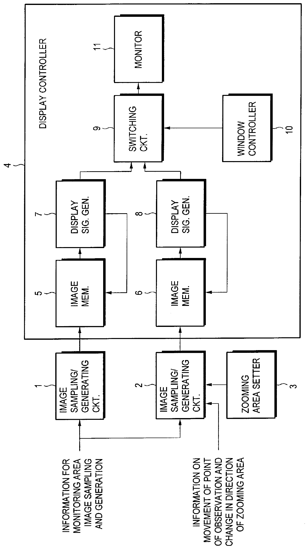
FIG. 14 is a block diagram showing a control circuit configuration of a radar according to the second embodiment. The configuration of FIG. 14 differs from that of the first embodiment shown in FIG. 7 in that an output of a global positioning system (GPS) receiver 53 is entered to a setup parameter calculating circuit 36 of FIG. 14 whereas an output of the speed log 35 is entered to the setup parameter calculating circuit 36 of FIG. 7. The configuration of FIG. 14 is otherwise identical to that of FIG. 7.

FIG. 15 is a flowchart depicting an operational sequence for setting a zooming area within the whole radar coverage shown in the larger window E1 of FIG. 3. First, the setup parameter calculating circuit 36 checks whether a trackball provided at an input section 33 has been operated (step S41). When any trackball operation has been detected, the setup parameter calculating circuit 36 updates the pos...

third embodiment

A scanning sonar according to the invention is now described with reference to FIGS. 17 and 18.

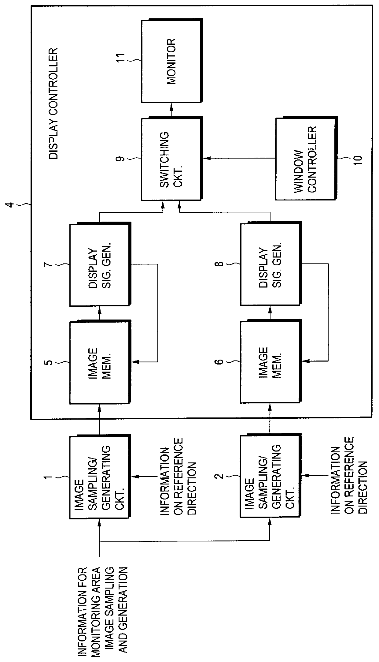
FIG. 17 is a block diagram showing a control circuit configuration of the scanning sonar according to the third embodiment. Referring to the block diagram, A / D converters 21 and 22 convert incoming echo signals of a pair of channels into digital data and image memories 27 and 28 store the A / D-converted echo signals in their appropriate addresses. Write address generators 31 and 32 generate write addresses for the image memories 27 and 28, respectively, based on various timing signals including transmit / receive timing signals which control transmission and reception of ultrasonic pulses. A setup parameter calculating circuit 36 receives information on settings of range scales and the central points of images to be displayed in a larger window E1 and smaller window E2 entered via an input section 33 as well as the ship's heading and speed entered from a compass 34 and a speed log 35, respect...


PUM


Abstract

In one aspect of the invention, an image monitoring apparatus has a plurality of display windows created on a single screen for presenting target objects existing within a monitoring area, wherein an image of the monitoring area and an image of a particular portion of the monitoring area are displayed in separate display windows with reference directions of the individual images aligned independently of each other with a specified direction of the screen. In another aspect of the invention, an image monitoring apparatus capable of detecting target objects existing within a monitoring area and displaying an image of detected target objects on a screen makes it possible to set a particular area of interest within the monitoring area, wherein the apparatus continuously displays a target image of the area of interest regardless of a movement of a point of observation or a change in the direction of the area of interest.

Description

1. Field of the InventionThe present invention relates to an image monitoring apparatus such as a radar apparatus, a scanning sonar apparatus and a course plotting apparatus, for example.2. Description of the Prior ArtConventionally known technology used in a radar apparatus, for example, includes a zoom function which allows an operator to enlarge a desired portion of a whole radar coverage for observing smaller details within a particular area of interest. A commonly used technique in this kind of zoom function is to place a cross-hair cursor (a pair of intersecting lines for specifying a particular location on a screen) at the center of an area to be zoomed and operate a key to execute the zoom function, whereby an enlarged image of the area around the cursor position is presented on the screen at a varied range scale.A conventional scanning sonar transmits and receives ultrasonic signals at a set tilt angle and provides a two-dimensional presentation of underwater objects detect...

Claims


Application Information

Patent Timeline
Patent Type & Authority Patents(United States)
IPC IPC(8): G01S7/06G01S7/56G01S7/62G01S7/04G01S7/22G01S7/14G01S7/295G01S13/00
CPCG01S7/06G01S7/22G01S7/62G01S7/6281
Inventor KIYA, YOSHIYUKI
Owner FURUNO ELECTRIC CO LTD
Why Eureka
Try Eureka