
Image forming device

a technology of forming device and paper size, which is applied in the direction of electrographic process apparatus, instruments, optics, etc., can solve the problems of difficult to check whether or not the paper size displayed at the operation display panel unit matches the paper size set at the operation display panel unit, and may occur jams, etc., to achieve convenient checking and reliably set the paper size

Inactive Publication Date: 2008-02-21
MURATA MASCH LTD
View PDF6 Cites 6 Cited by
  • Summary
  • Abstract
  • Description
  • Claims
  • Application Information

AI Technical Summary

Benefits of technology

[0009]In order to overcome the problems described above, preferred embodiments of the present invention provide an image forming device in which it is easy to check whether or not a size of papers placed on a manual paper feed tray matches a paper size set at an operation display panel unit. Further, it becomes possible to reliably set the paper size without forgetting the setting.
[0011]With the above-described configuration, the size can be set by using the paper setting dial attached to the manual paper feed tray. Moreover, a size setting operation can be easily carried out while checking the placed paper, and the setting is reliably carried out. When the placed paper matches the size set at the paper setting dial, information on the size of the placed paper is reliably output by the paper size detection unit to the device main body, and thus, a paper transporting operation can be stably carried out.
[0012]When the open-close detection sensor of the manual paper feed tray detects the opened status, the paper transportation control is performed based on the detection signal from the paper size detection unit. In the above-described configuration, only under a state in which the manual paper feed tray is under the opened status and the paper can be fed manually, paper transportation can be carried out based on the detection signal from the paper size detection unit. Thus, a manual paper feeding operation can be reliably carried out.
[0013]Since the paper setting dial is arranged to have a color different from the color of the manual paper feed tray, a user can easily view and check the paper setting dial, and consequently, the setting operation of the paper size is prompted when the paper is placed on the manual paper feed tray.
[0014]Further, the paper setting dial can be arranged on the front surface side of the device, i.e., on a side on which the user stands when placing the papers on the manual paper feed tray. Accordingly, the paper setting dial can be easily viewed and checked when placing the paper, and the setting will not be forgotten.

Problems solved by technology

However, when using cardboard or the like, which cannot be fed easily from the paper feed cassette, the image forming processing is performed by feeding such materials from a manual paper feed tray.
Therefore, a problem is that it is difficult to check whether or not the paper size displayed at the operation display panel unit matches the paper size displayed on the paper feed cassette that is positioned apart from the operation display panel unit.
In particular, when feeding the paper from the manual paper feed tray on which various papers are to be placed, it is difficult to check whether or not the size of the placed paper matches the paper size set at the operation display panel unit.
In such a case, problems such as a jam may occur when placing the paper on the manual paper feed tray without checking the paper size set at the operation display panel unit.

Method used


Image

  • Image forming device
  • Image forming device
  • Image forming device

Examples


Embodiment Construction

[0020]A detailed description will be made of preferred embodiments of the present invention. Since the preferred embodiments described below are preferred specific examples of the present invention, the preferred embodiments may have various technical limitations. However, the present invention is not limited to the preferred embodiments as long as it is not specified in the following description that the present invention is limited to the preferred embodiments.

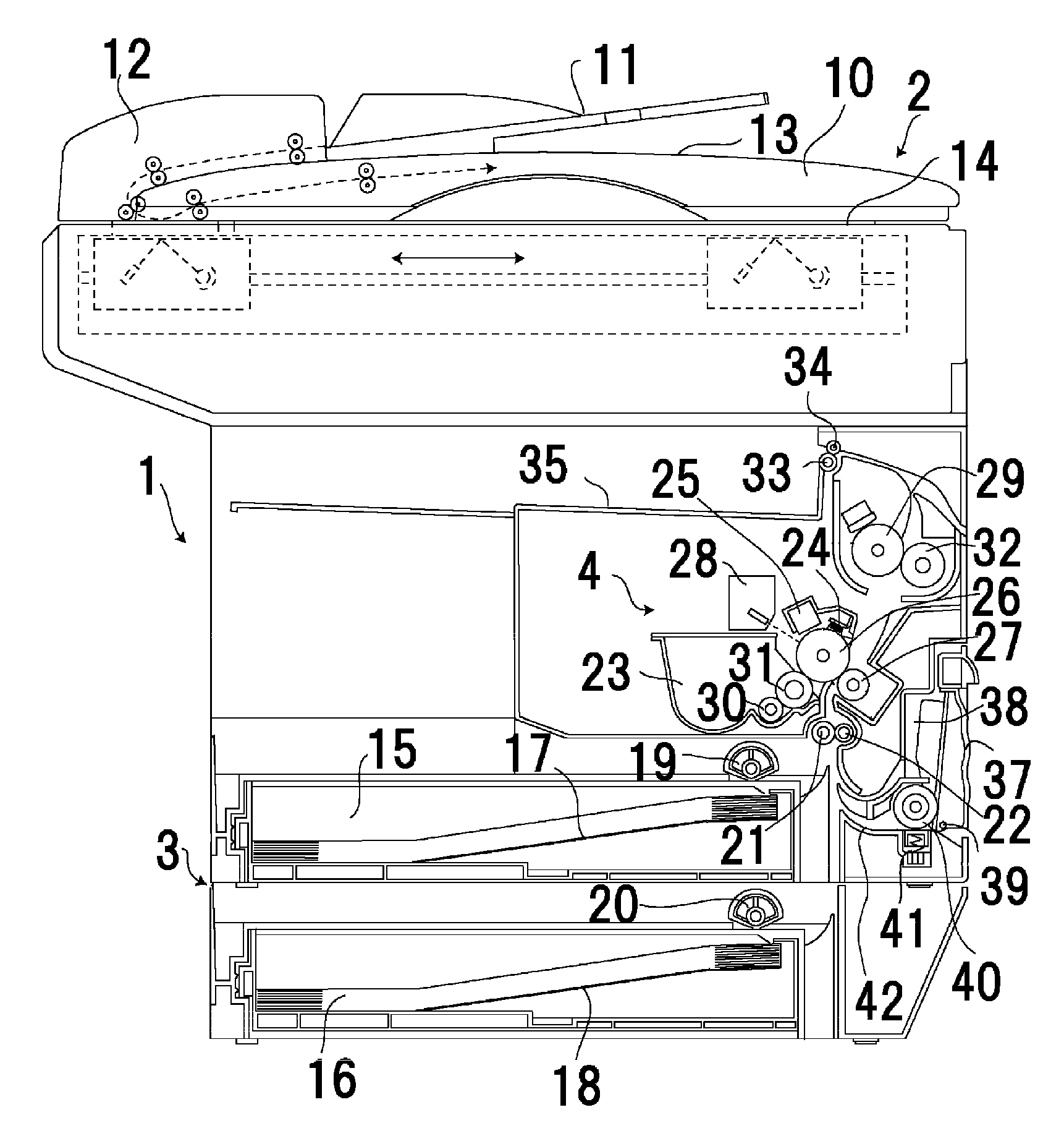
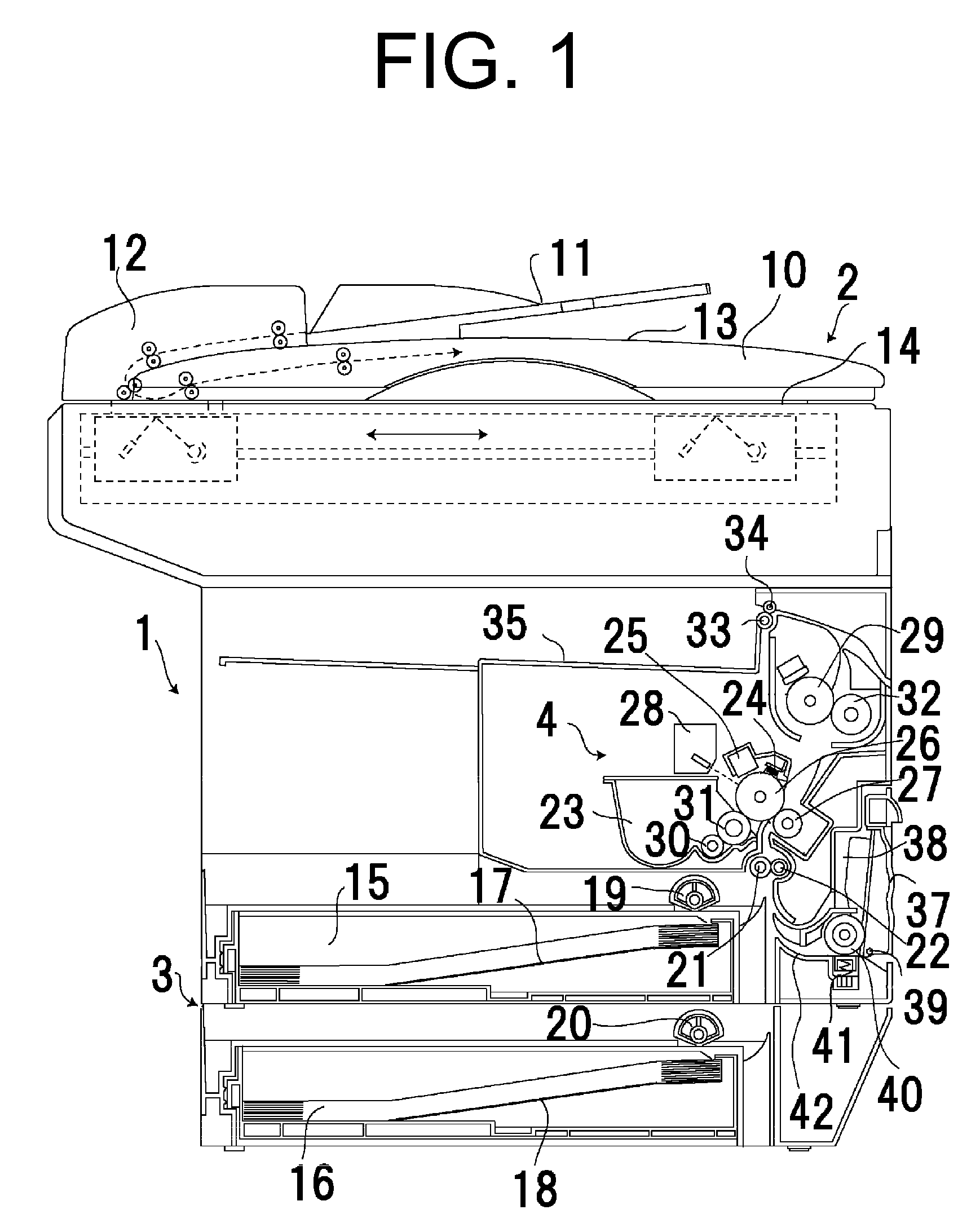
[0021]FIG. 1 is a schematic sectional view of an overall image forming device according to preferred embodiments of the present invention. An original document scanning unit 2 is arranged on an upper portion of an image forming device 1. A paper feeding unit 3 and a recording unit 4 are subsequently arranged from a bottom surface on a lower portion of the image forming device 1.

[0022]At the original document scanning unit 2, an original document placed on an original document tray 11 mounted on an original document cover 10 ...


PUM


Abstract

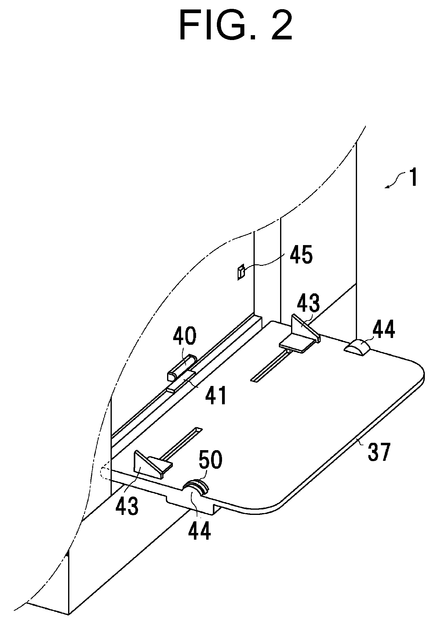
In an image forming device, on a farther end side from each paper guide of a manual paper feed tray, a pair of protruding portions are arranged such that each of the protruding portions is arranged on either side to prevent oblique movement of papers. One of the protruding portions is provided with a paper setting dial rotatably attached thereto. Marks indicating a paper size are displayed on a circumferential surface of the dial such that the size can be set by turning the dial in accordance with the size of the placed paper. The paper setting dial is attached on a side on which a user stands when placing the papers.

Description

BACKGROUND OF THE INVENTION[0001]1. Field of the Invention[0002]The present invention relates to an image forming device such as a copier, a facsimile machine, and a printer.[0003]2. Description of the Related Art[0004]An image forming device which uses a photoconductive drum, for example, as an image carrier, charges and exposes a surface of the photoconductive drum to form an electrostatic latent image, visualizes the electrostatic latent image by adhering toner to the image, and transfers the adhered toner to a paper, is known as an electrophotographic image forming device. In such an image forming device, image forming processing is performed by transporting papers of various sizes, and the papers of a frequently-used size are placed in a paper feed cassette and fed to the image forming device. However, when using cardboard or the like, which cannot be fed easily from the paper feed cassette, the image forming processing is performed by feeding such materials from a manual paper...

Claims


Application Information

Patent Timeline
IPC IPC(8): G03G21/00
CPCG03G2215/00734G03G15/6514
Inventor MOTOYOSHI, KOICHI
Owner MURATA MASCH LTD
Learn More