Unknown

Active Publication Date: 2008-02-21
KARL STORZ GMBH & CO KG
View PDF3 Cites 21 Cited by
  • Summary
  • Abstract
  • Description
  • Claims
  • Application Information

AI Technical Summary

Benefits of technology

[0021] With a practical embodiment for the configuration of the limiting device, it is proposed that two opposite contact surfaces configured as recesses should be positioned on the tool actuation element and that a contact element should be mounted in a recess in the hollow shaft and, with the tool actuation element and hollow shaft installed, should be in essentially form-locking contact with one of the contact surfaces of the tool actuation element. When the tool actuation element and hollow shaft are installed and connected with the handle, the contact element, interacting in essentially form-locking conta

Problems solved by technology

The bayonet-type connection has proved itself in practice, but its us

Method used


Image

  • Unknown
  • Unknown
  • Unknown

Examples


first embodiment

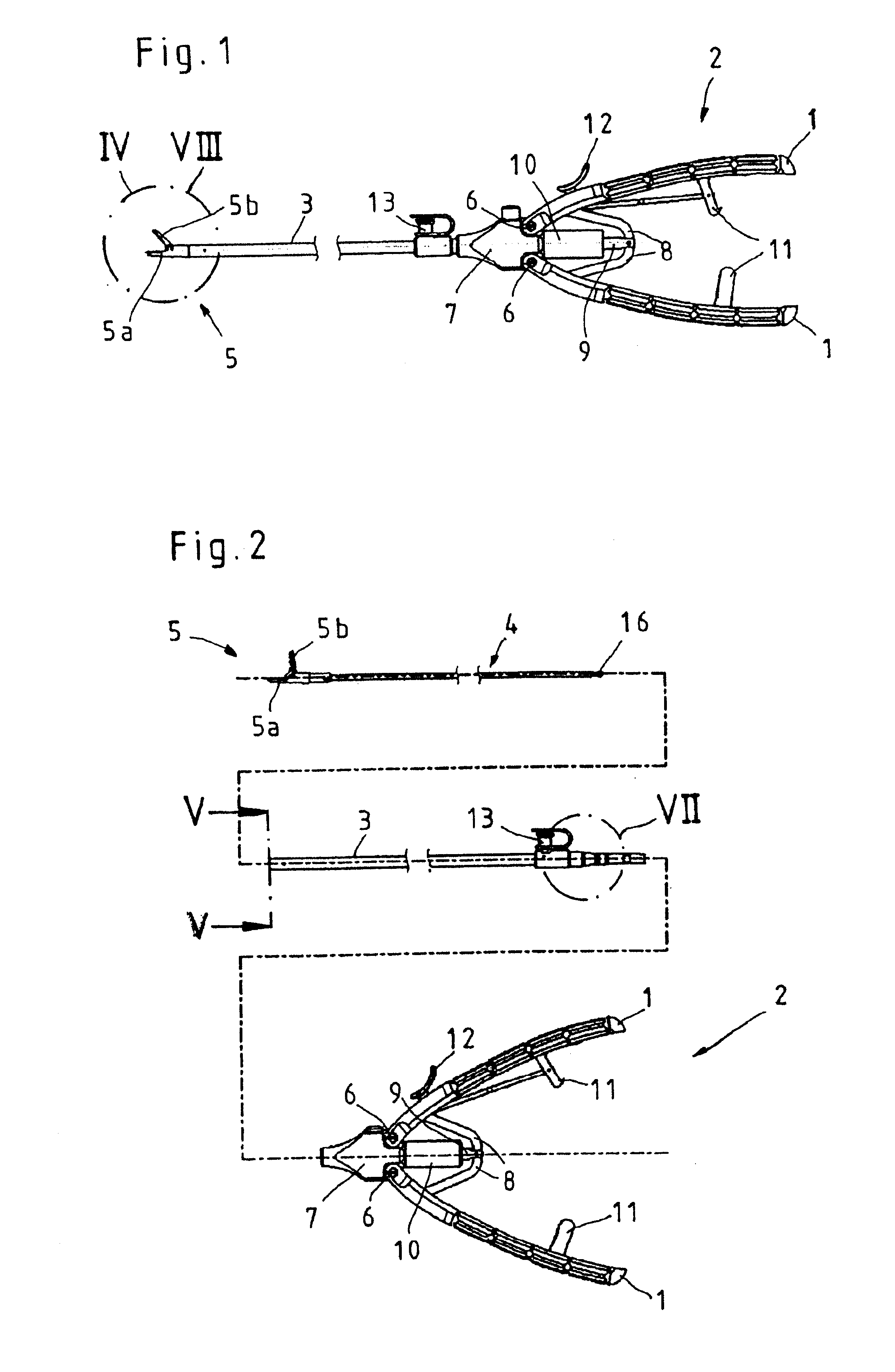
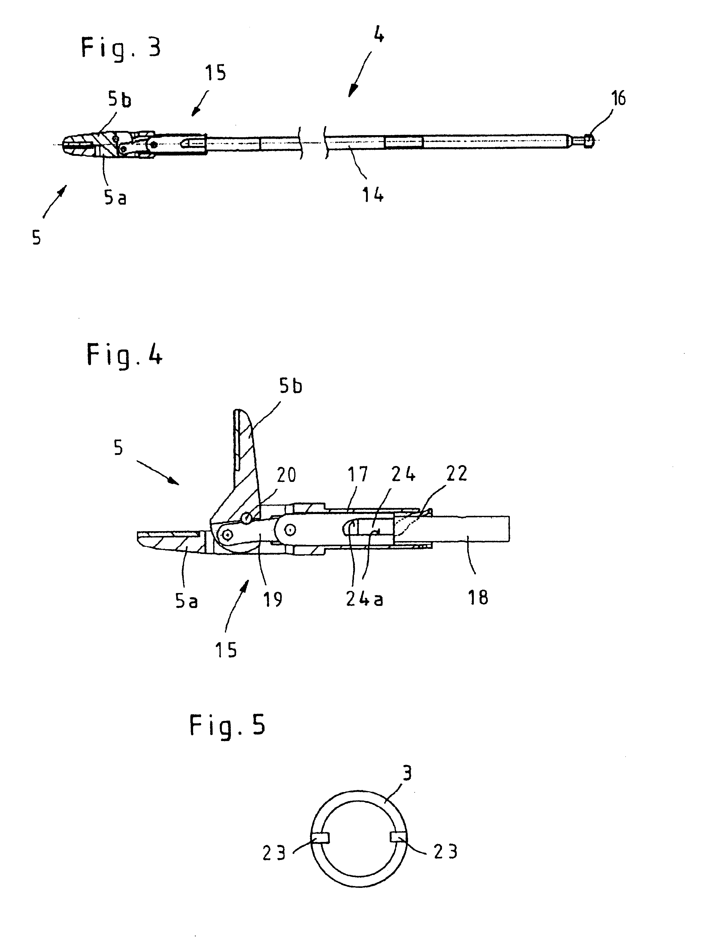
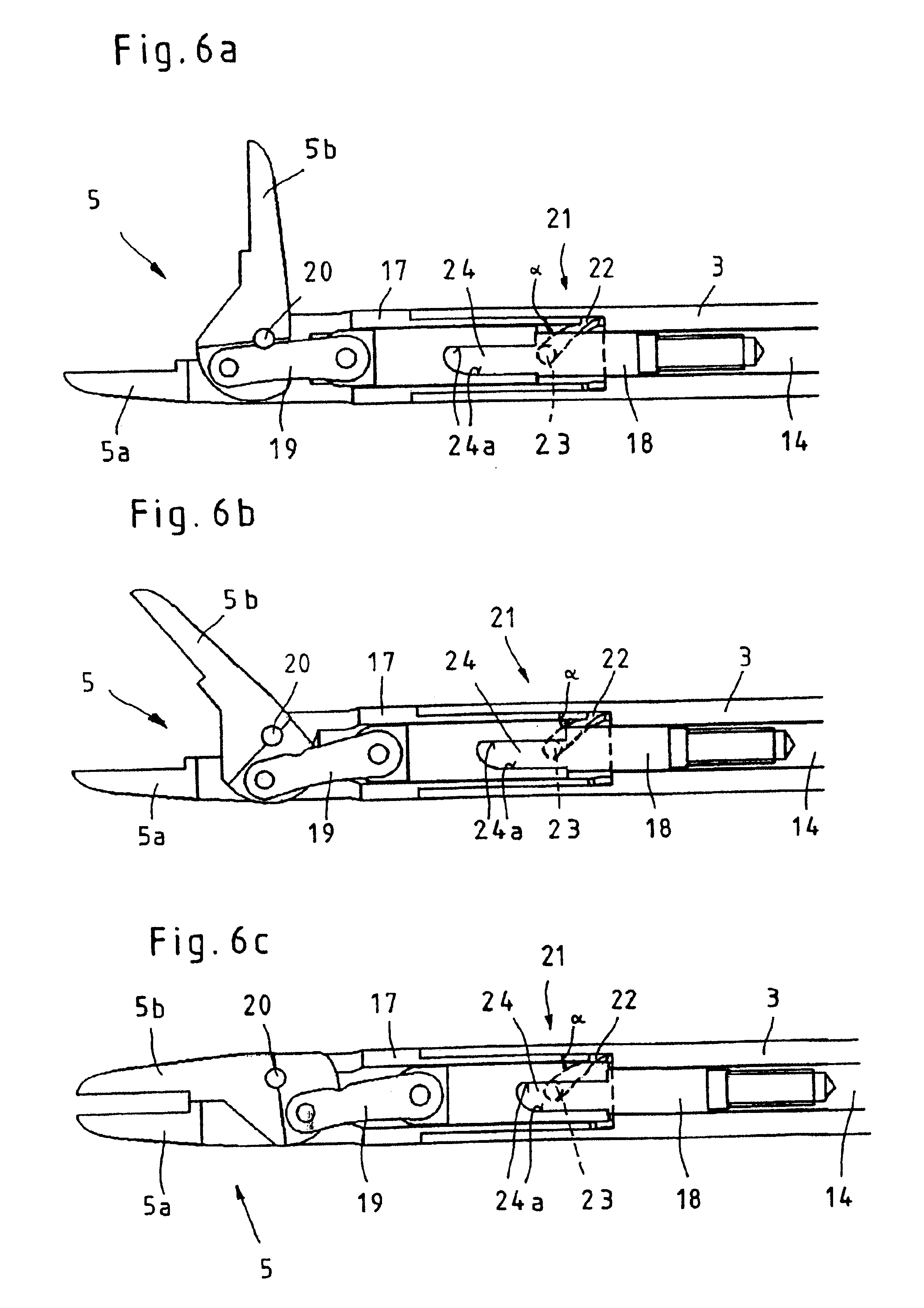
[0056] In the first embodiment shown in FIGS. 4 and 6a through 6c, the tool assembly 15 consists of a sleeve 17, which is configured as a single unit with a jaw member of the tool 5 that is configured as a rigid jaw member 5a. A tool shaft 18 is mounted in the sleeve 17 so that it can slide in the axial direction, and said shaft is connected on the distal side with the rotatable jaw member 5b of the tool 5 by an articulated lever 19 and on the proximal side can be connected firmly with the rod base body 14. To allow the axial sliding of the push-pull rod 4 to be transmitted directly and as free as possible of play to the rotatable jaw member 5b by the tool shaft 18, the articulated lever 19 is mounted so that it can rotate both on the rotatable jaw member 5b and on the tool shaft 18. The sleeve 7 equipped with a rigid jaw member 5a and the tool shaft 18 are connected or coupled to one another by the rotatable jaw member 5b and a rigid rotation axle 20 of the rotatable jaw member 5b,...

second embodiment

[0074] In the second embodiment, shown in FIGS. 8a through 9c, the tool assembly 15 consists likewise of a sleeve 17, which is configured as a single unit with a jaw member of the tool 5 that is configured as a rigid jaw member 5a. The rod base body 14 of the push-pull rod 4 is mounted so that it can slide in the axial direction in the sleeve 17 and on the distal side it is connected with the rotatable jaw member 5b of the tool 5. To allow the axial sliding of the push-pull rod 4 to be transmitted directly onto the rotatable jaw member 5b, and as free of play as possible, the rod base body 14 is mounted rotatably on the rotatable jaw member 5b. The sleeve 17 equipped with the rigid jaw member 5a and the rod base body 14 are connected or coupled to one another by the rotatable jaw member 5b and a rigid rotation axle 20 of the rotatable jaw member 5b, in such a way that the rotation axle 20 is mounted in the sleeve 17.

[0075] Finally, FIGS. 8 through 9c according to this second embodim...

embodiment

ACCORDING TO FIGS. 6A THROUGH 6

[0079] To start the assembly, the tool 5 is converted into the installation position illustrated in FIG. 6a by opening the jaw members 5a and 5b, and in said position the rotatable jaw member 5b is found in an extremely wide-opened position, into which the jaw member 5b of the assembled tubular instrument cannot be converted.

[0080] In this installation position the hollow shaft 3, with its distal end foremost, is pushed onto the push-pull rod 4 until the distal end is in contact with the sleeve 7 of the tool assembly 15. The hollow shaft 3 and push-pull rod 4 components are coupled then by rotating the components with respect to one another until the control pegs engage in the guide tracks 22. Then the components 3 and 4 are rotated further with respect to one another until the control peg 23 has reached the end of the guide track 22.

[0081] If the push-pull rod 4 is drawn in the axial direction all the way to the proximal end or else the jaw members ...


PUM


Abstract

The invention relates to a tubular medical instrument having a hollow shaft, a handle positioned on the proximal end of the shaft, and at least one tool actuation element that is positioned in the hollow shaft and has on its distal end a tool, wherein the tool actuation element can be coupled with at least one actuation mechanism of the handle to actuate the tool and wherein the tool actuation element and the hollow shaft can be detachably connected to one another by a coupling mechanism. To create a coupling mechanism that is essentially free of any play and is simple to operate, it is proposed with the invention that the stopping of the coupling mechanism between the tool actuation element and the hollow shaft should be dependent on the position of the tool.

Description

CROSS-REFERENCE TO RELATED APPLICATIONS [0001] The present application claims priority of German patent application No. 10 2006 038 516.0 filed on Aug. 17, 2006, the content of which is incorporated herein by reference. FIELD OF THE INVENTION [0002] The invention relates to a tubular medical instrument having a hollow shaft, a handle positioned on the proximal end of the shaft, and at least one tool actuation element that is positioned in the hollow shaft and has on its distal end a tool, and wherein the tool actuation element can be coupled with at least one actuation mechanism of the handle to actuate the tool and wherein the tool actuation element and the hollow shaft can be detachably connected to one another by a coupling mechanism. BACKGROUND OF THE INVENTION [0003] Tubular medical instruments of this type are used, for instance, in the configuration as needle holder, in endoscopic surgery. Because of increasingly stringent hygienic demands, it is more and more often required ...

Claims


Application Information

Patent Timeline
IPC IPC(8): A61B17/28
CPCA61B17/00234A61B17/29A61B2017/0046A61B2017/2939A61B2017/2902A61B2017/292A61B2017/2901
Inventor RENGER, UWEBLOCHER, MARTINBACHER, UWE
Owner KARL STORZ GMBH & CO KG
Why Eureka
Try Eureka